Spherical hinged connection device for two sliding shafts

A technology of axial grooves and balls, applied in the field of two sliding shaft devices, to achieve the effect of easy installation

Active Publication Date: 2014-08-13
罗伯特博世汽车转向旺多姆股份公司
View PDF4 Cites 2 Cited by
  • Summary
  • Abstract
  • Description
  • Claims
  • Application Information

AI Technical Summary

Problems solved by technology

This satisfactory solution to smooth sliding raises the issue of angular stiffness, since it is directly proportional to the stiffness and preload of the spring

Method used


Image

  • Spherical hinged connection device for two sliding shafts
  • Spherical hinged connection device for two sliding shafts
  • Spherical hinged connection device for two sliding shafts

Examples


Embodiment Construction

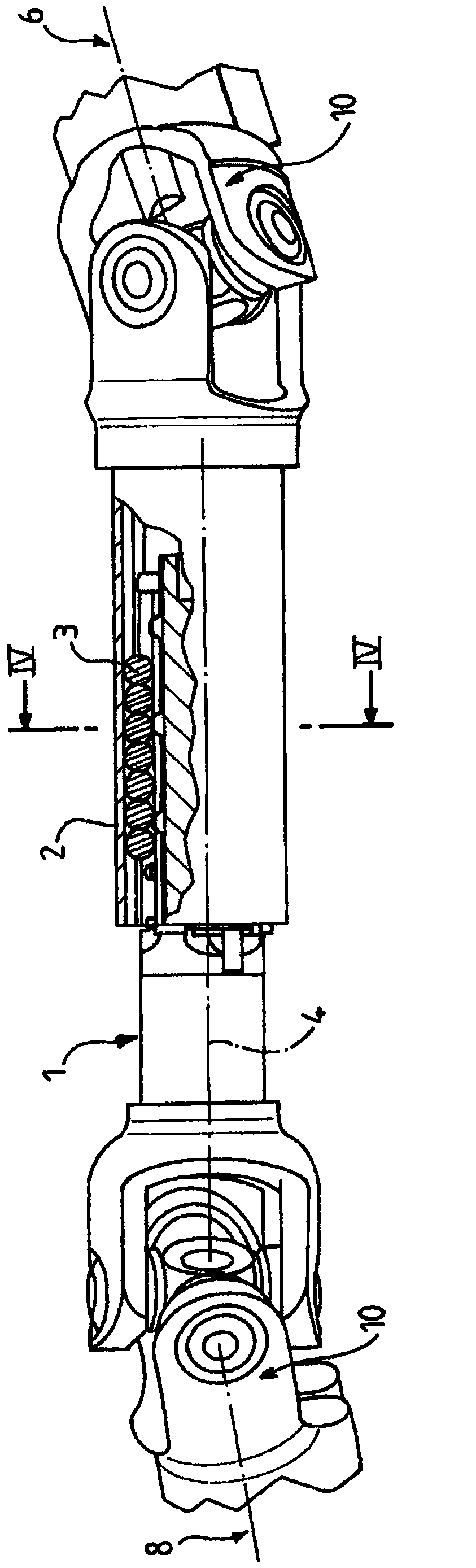
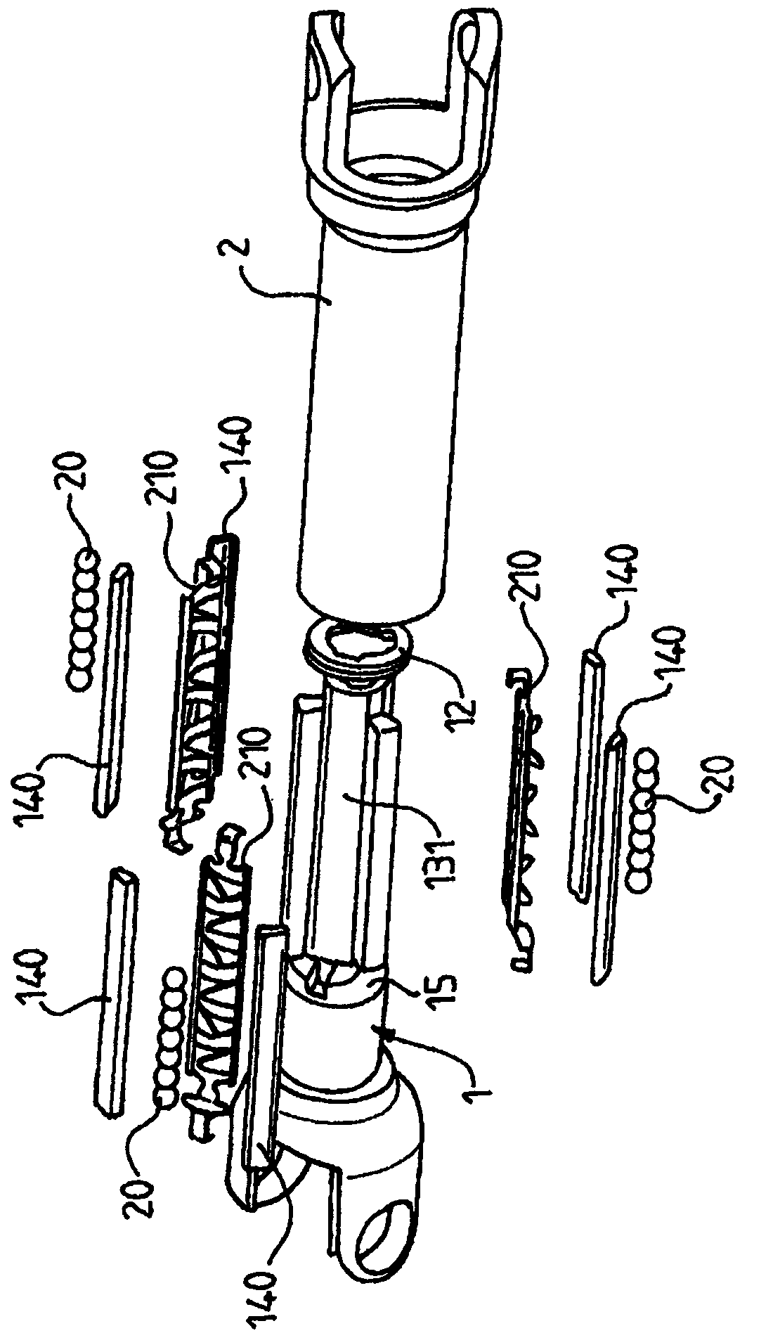
[0073] The invention relates to a rotary coupling device for two shafts sliding into each other along their common axis.

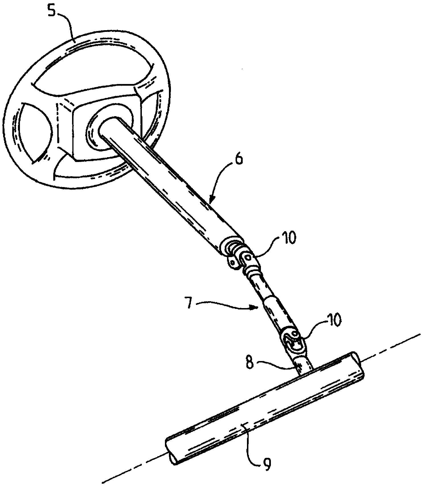
[0074] The coupling device is particularly well suited to applications such as figure 1 In a motor vehicle steering system of the kind schematically depicted in .

[0075] The steering system described comprises a steering column with an upper column part 6, also called column top, and a middle column part 7, also called center axis.

[0076] The upper pillar part 6 is connected by its upper end to the steering wheel 5 and by its lower end to the middle pillar part 7 .

[0077] The middle column part 7 is connected by its upper end to the upper column part 6 and by its lower end to the steering gear box 8 of the steering rod 9 .

[0078] The middle column section 7 is connected at each end to the upper column section 6 by a universal joint, indicated at 10 , and to the steering gearbox 8 by a universal joint, also indicated at 10 .

[0079] In the next ...


PUM


Abstract

The invention relates to a steering column, which comprises an inner shaft, an outer shaft, columns of spherical objects, rigid rolling rail parts and elastic elements, wherein an axial groove of one of the inner and outer shafts is provided with two sunken support surfaces; each rigid rolling rail part comprises raised pivoting parts with raised pivoting surfaces and supporting parts with supporting surfaces, which are positioned on each side of a middle plane; the raised pivoting surfaces contact the sunken support surfaces; the supporting surfaces are pressed against and support the spherical objects; the elastic elements are positioned in the axial groove of one of the inner and outer shafts, and are pressed against the spherical objects to push and press the two rolling rail parts, so that torque transmission is avoided in a stationary state but is performed in a running state; each spherical object simultaneously contacts the two rolling rail parts and the axial groove of one of the inner and outer shafts; the radius of each raised pivoting surface of the two rolling rail parts is greater than that of the corresponding sunken support surface contacting the raised pivoting surface, so that two contact areas of pivoting axes parallel to a common axis can be defined and determined.

Description

[0001] The application for this patent invention is the international application number PCT / FR2008 / 000874, the international application date is June 20, 2008, the application number entering the Chinese national phase is 200880129849.1, and the name is "A hinged connection for two sliding shafts The divisional application of the invention patent application for the ball coupling device. technical field [0002] The invention relates to a device for rotatably coupling two sliding shafts sliding along their common axis. By applying the coupling device of the invention to the middle column part connected to the steering gearbox or to the upper column part connected to the steering wheel, the coupling device of the invention is particularly suitable for use in motor vehicle steering columns. Background technique [0003] Especially in the case of the intermediate axis, the latter has cardan joints at each end: one cardan joint is connected to the kinematic input of the steerin...

Claims


Application Information

Patent Timeline
Patent Type & Authority Applications(China)
IPC IPC(8): F16D3/06
Inventor C·巴尔A·简维尔
Owner 罗伯特博世汽车转向旺多姆股份公司
Why Eureka
Try Eureka