
Method for measuring gravity acceleration by sleeving cylinder to increase compound pendulum length

A gravitational acceleration and cylinder technology, which is applied to experimental equipment and experimental fields, can solve the problems of cumbersome and time-consuming data measurement and processing, long intervals, etc., and achieve the effect of simple and clear measurement devices and measurement processes, and simple and fast data processing

Inactive Publication Date: 2014-08-13
SICHUAN UNIV
View PDF5 Cites 5 Cited by
  • Summary
  • Abstract
  • Description
  • Claims
  • Application Information

AI Technical Summary

Problems solved by technology

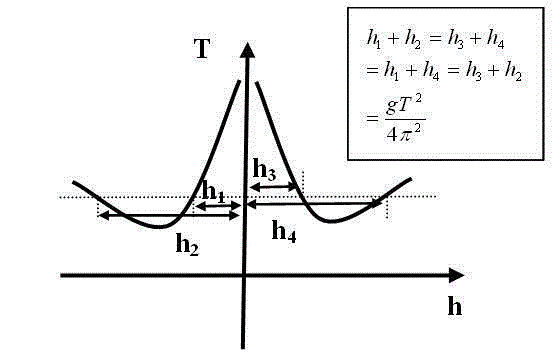
[0005] Since the measurement points are discrete data, the abscissa interval of the discrete data is generally 2cm, and the interval is relatively long. Generally, it is impossible to find that the cycle of the four measurement points is exactly the same. The cycle curve is a traced curve, which deviates from the real curve, so make a The four points where the horizontal line intersects the deviated h-T curve, the coordinate values ​​of the abscissa read from the four points also have deviations, so in addition to the error of the experiment itself, the graphical calculation method also brings a large deviation, Moreover, the data measurement process and processing process are cumbersome and time-consuming

Method used


Image

  • Method for measuring gravity acceleration by sleeving cylinder to increase compound pendulum length
  • Method for measuring gravity acceleration by sleeving cylinder to increase compound pendulum length
  • Method for measuring gravity acceleration by sleeving cylinder to increase compound pendulum length

Examples


Embodiment Construction

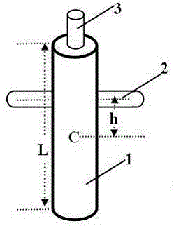
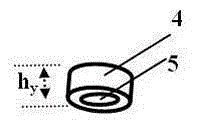
[0013] The pendulum rod of compound pendulum consists of a thin rod 1 and a cylinder 4 inserted into the sleeve rod 3;

[0014] The hanging rod 2 is fixed on the thin rod 1, the central axis (center line) of the thin rod 1 is perpendicular to and intersects with the central axis (center line) of the hanging rod 2, and the two ends of the hanging rod 2 are placed in a pair of grooves, and put in After the groove, the central axis of the hanging rod 2 is horizontal, and the hanging rod is cylindrical, and the thin rod 1 can swing back and forth around the central axis of the hanging rod 2.

[0015] The distance between the central axis of the hanging rod 2 and the centroid C of the thin rod 1 is h, h>0.289L, preferably h is 0.30L-0.35L, the sleeve rod 3 is fixed on the upper end of the thin rod 1, and the sleeve rod 3 and the thin rod 1 have The common central axis (central line), the cylinder 4, the sleeve rod 3, and the thin rod 1 are made of the same material, and the cross-s...


PUM


Abstract

The invention provides a method for measuring the gravity acceleration by sleeving a cylinder to increase the compound pendulum length, and relates to the field of physical experiment devices and experimental methods. The method is designed to overcome the defect that the measurement process and the data processing process are complex and high in time consumption and to reduce deviation introduced by calculation. According to the technical scheme, a cylindrical hanging rod is fixed to a thin rod, the central axis of the thin rod and the central axis of the hanging rod are perpendicular and intersect, the two ends of the hanging rod are placed in a pair of grooves, the central axis of the hanging rod is horizontal after the two ends of the hanging rod are placed in the grooves, and the thin rod can swing around the central axis of the hanging rod in a reciprocating mode; the distance h between the mass center C of the thin rod and the central axis of the hanging rod is larger than 0.30 time of the length L of the thin rod and smaller than 0.35 time of the length L of the thin rod; a sleeve rod is fixed to the upper end of the thin rod and shares the same central axis with the thin rod, the cylinder, the sleeve rod and the thin rod are made of the same material, the periphery of the cross section of the cylinder and the periphery of the cross section of the thin rod are the same in shape and equal in size, and the gap between the cylinder and the sleeve rod is too small and can be omitted. The method has the advantages that a measurement device and the measurement process are simple and clear, and data processing is easy and rapid.

Description

technical field [0001] The invention relates to the field of experimental equipment and experimental methods, in particular to the experiment of measuring the acceleration of gravity with a compound pendulum in a physical experiment. Background technique [0002] In the experiment of measuring the acceleration of gravity with the compound pendulum in the university physics experiment, a long pendulum rod with equidistant circular holes is generally used. There are scales on the surface of the pendulum rod. The hole is hung on the hanging rod (the hanging rod is fixed on the bracket) to swing, measure the swing cycle, record the position coordinates of each hole when hanging (the distance from the round hole to the center of the swing rod, or the origin of other coordinates) and the The swing period when the circular hole is suspended, and then draw a graph on the coordinate paper, and use the graphical method to calculate the acceleration of gravity. [0003] "University Ph...

Claims


Application Information

Patent Timeline
IPC IPC(8): G09B23/10G01V7/12
Inventor 饶大庆胡再国李娟
Owner SICHUAN UNIV
Learn More