Three-station isolating switch

A technology of isolating switch and three-station, which is applied in the direction of air switch components, etc., which can solve the problem that the operation reliability affects the operation safety of the isolating switch, the operation reliability and maintenance performance need to be improved, and the service life of the knife switch and static contact is reduced. and other problems, to achieve the effect of good action reliability, simple structure, and simple electric operation

Active Publication Date: 2014-08-13
XIAMEN XEC ELECTRIC
View PDF8 Cites 17 Cited by
  • Summary
  • Abstract
  • Description
  • Claims
  • Application Information

AI Technical Summary

Problems solved by technology

In the structure of the isolating switch, the three functions of closing, opening and grounding are realized through the rotation of the knife switch. Usually, one end of the knife switch is connected to the isolated static contact, and the rotation of the knife switch is completed by an operating mechanism. , the operational reliability of the operating mechanism directly affects the performance and operational safety of the isolating switch. At the same time, the operating mechanism is the place where failures often occur in the three-position isolating switch. The maintenance performance of the operating mechanism will affect the power failure time of the line
The traditional operating mechanism usually adopts manual operation, which is difficult to realize circuit operation, and the operation reliability and maintenance performance need to be improved
[0003] On July 04, 2012, an application for invention with the application number 201110439906.X and the name "A Three-Pos

Method used


Image

  • Three-station isolating switch
  • Three-station isolating switch
  • Three-station isolating switch

Examples


Example Embodiment

[0045] The present invention will be further described in detail below with reference to the drawings and specific embodiments.

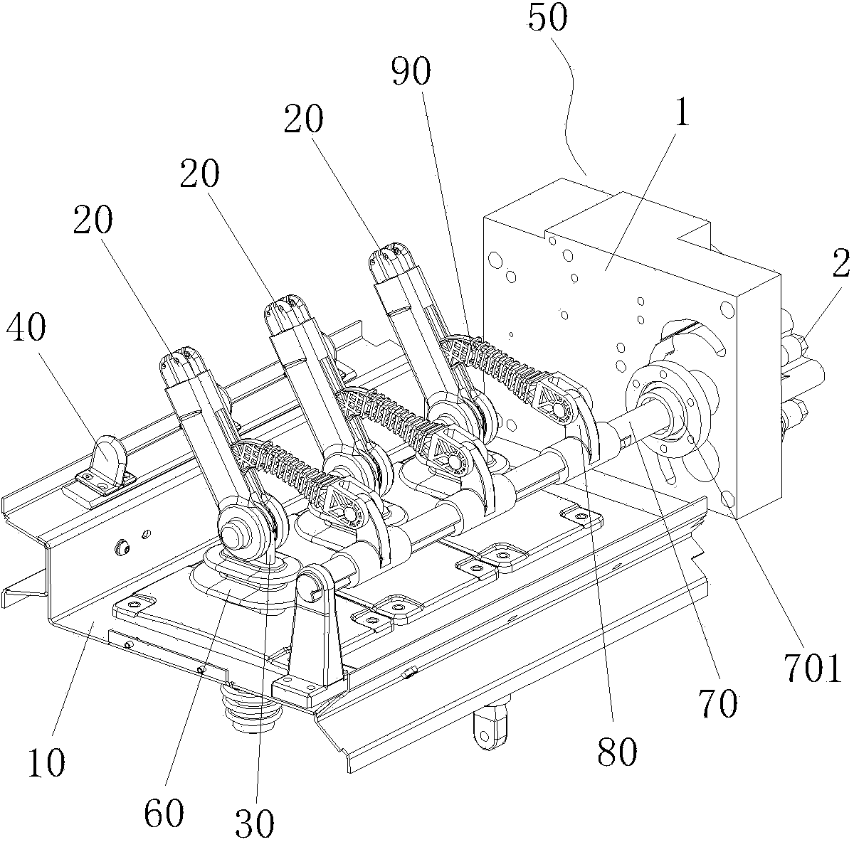
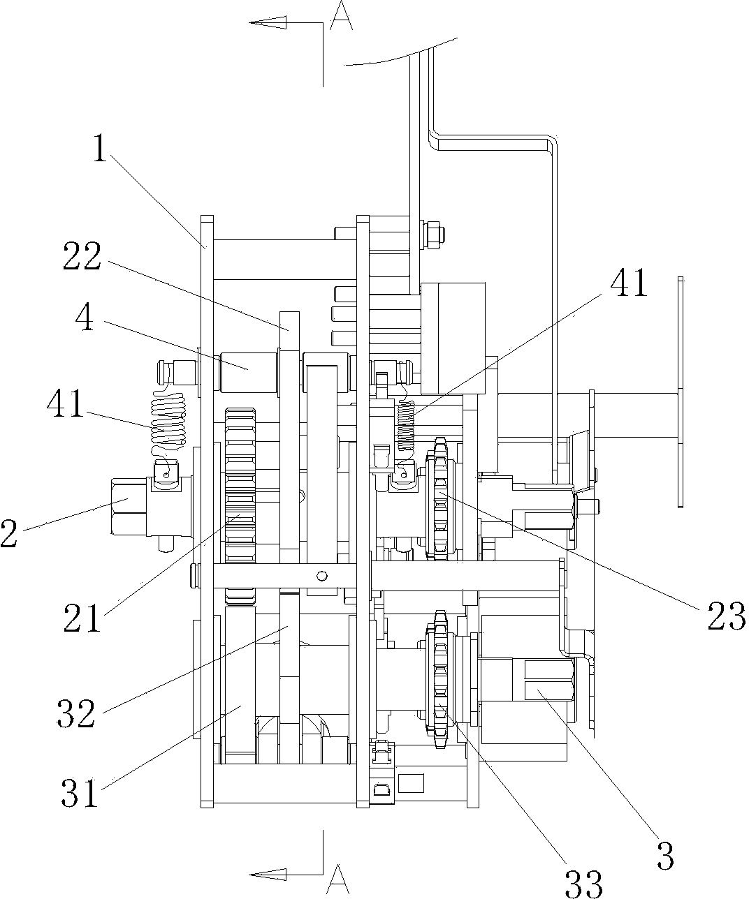
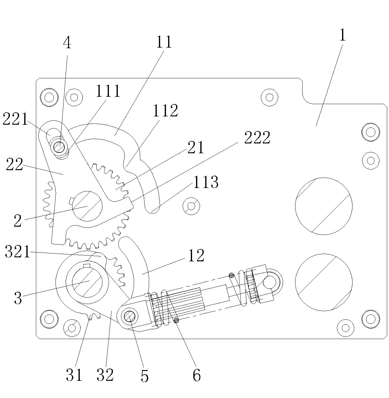
[0046] Figure 1 to Figure 8 As shown, a three-station isolating switch includes a frame 10, three knife switches 20, three static contacts 30, three grounding contacts 40, and an operating mechanism 50. Three insulating supports 60 are fixed on the frame 10 , The three static contacts 30 are fixed in the middle of the three insulating supports 60, one end of the three knife switches 20 are respectively connected to the three static contacts 30, and the three ground contacts 40 are fixed on the side of the frame 10 and the three The two knife gates 20 cooperate, the other side of the frame 10 is pivotally connected to a rotating shaft 70, the rotating shaft 70 is fixedly connected to three first turning arms 80, and the three first turning arms 80 are respectively connected to the three through three insulating rods 90. The middle of a knife gate 20;

...


PUM


Abstract

The invention discloses a three-station isolating switch which comprises a rack, disconnecting links, fixed contacts, grounding contacts and an operating mechanism. The rack is connected with a rotating shaft in a pivotal mode, and the rotating shaft drives the disconnecting links to rotate through first connecting levers and insulating pull rods. The operating mechanism comprises a shell, the shell is connected with a first operating shaft and a second operating shaft in a pivotal mode, and the first operating shaft is fixedly connected with the rotating shaft. The first operating shaft is fixedly connected with a first gear and an isolating limiting plate. The isolating limiting plate is provided with a first positioning hinge pin in a penetrating mode, and the two ends of the first position hinge pin are connected with the first operating shaft through two tension springs. The shell is provided with a switching-on groove, a switching-off groove and grounding grooves which are matched with the first positioning hinge pin. The second operating shaft is fixedly connected with a second gear and a connecting lever, wherein the connecting lever is connected with the shell through a second positioning hinge pin and a compression spring. The shell is provided with a second arc hole which is matched with the second positioning hinge pin. The second gear is not matched with the first gear in a switching-on state and a switching-off state and is matched with the first gear in a grounding state. The three-station isolating switch is compact in structure, reliable in action and convenient to maintain.

Description

Technical field [0001] The invention relates to a three-station isolating switch. Background technique [0002] In the power distribution system, the three-position isolating switch is usually used in the switch cabinet. The three-position isolating switch refers to the isolating switch that can realize the three functions of closing, opening and grounding. In the structure of the isolating switch, the three functions of closing, opening and grounding are realized by the rotation of the knife switch. Usually, one end of the knife switch is connected with an isolated static contact, and the rotation of the knife switch is completed by an operating mechanism. , The operation reliability of the operating mechanism directly affects the performance and safety of the isolating switch. At the same time, the operating mechanism is the place where failures often occur in the three-position isolating switch. The maintenance performance of the operating mechanism will affect the power failu...

Claims


Application Information

Patent Timeline
IPC IPC(8): H01H31/04
Inventor 姚瑞灿陈荣财李艺强
Owner XIAMEN XEC ELECTRIC
Why Eureka
Try Eureka