Electric transmission line traveling wave differential protection method

A technology for differential protection and transmission lines, applied to emergency protection circuit devices, electrical components, etc., can solve problems such as lack of quantitative analysis, and achieve the effect of simple setting and sufficient theoretical basis

Active Publication Date: 2014-08-13
江苏燎源变压器有限公司
View PDF7 Cites 7 Cited by
  • Summary
  • Abstract
  • Description
  • Claims
  • Application Information

AI Technical Summary

Problems solved by technology

However, literature [8] only conducted qualitative analysis on this, and did not conduct quantitative analysis

Method used


Image

  • Electric transmission line traveling wave differential protection method
  • Electric transmission line traveling wave differential protection method
  • Electric transmission line traveling wave differential protection method

Examples


Embodiment Construction

[0029] The present invention will be described below in conjunction with the accompanying drawings and embodiments.

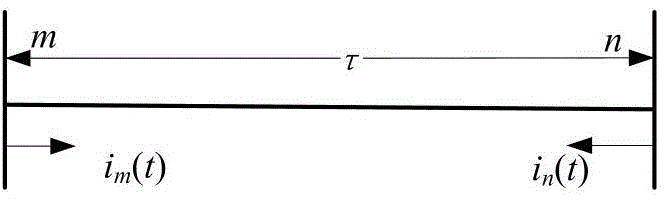
[0030] figure 1 where mn is a single-phase lossless line, the length is l, the wave velocity is v, τ=l / v is the propagation delay of the traveling wave on the entire length of the line, and the wave impedance is Z c , the positive direction of the current at both ends of the line is from the busbar to the line, and the current can be regarded as composed of the superposition of the forward current traveling wave and the reverse current traveling wave. The positive current traveling wave is defined as the left end flows to the right end, and vice versa is the reverse current traveling wave, then the current traveling wave at both ends (2 times) is:

[0031] i m + ( t ) ...


PUM


Abstract

The invention relates to an electric transmission line traveling wave differential protection method. It is supposed that the total length of a protected both-end electric transmission line is 1, setting valves of traveling wave differential protection are calculated according to the following steps: a zero mode unbalanced coefficient is calculated; the maximum zero mode forward-direction traveling wave current at the m end during an external earth fault in an electric transmission line area is determined, and the maximum zero mode backward-direction traveling wave current at the n end is determined; the setting valves of various phases of the forward-direction traveling wave differential protection and the backward-direction traveling wave differential protection are respectively calculated; the traveling wave differential protection is adjusted according to the setting valves of the various phases of the forward-direction traveling wave differential protection and the backward-direction traveling wave differential protection, failure recognition and judgment and protection movement on the traveling wave differential protection of the various phases are accordingly achieved. By means of the electric transmission line traveling wave differential protection method, protection error movement is not prone to being caused; the electric transmission line traveling wave differential protection method is easy to implement.

Description

technical field [0001] The invention relates to the field of relay protection for power system transmission lines, in particular to a traveling wave differential protection method. Background technique [0002] The principle of split-phase current differential protection for transmission lines is simple and its sensitivity is high. It is the main protection for UHV / EHV transmission lines. However, the distributed capacitive current in EHV / UHV transmission lines is large, which greatly affects the selectivity and reliability of the principle. The protection performance can be improved to a certain extent through the capacitive current compensation method, but due to the capacitive current in the fault transient process The frequency components are complex, and it is difficult to perform effective compensation [1-3] . [0003] Some scholars have proposed traveling wave differential protection based on traveling wave theory. This type of protection can be divided into two typ...

Claims


Application Information

Patent Timeline
Patent Type & Authority Applications(China)
IPC IPC(8): H02H7/26
Inventor 张艳霞宣文博徐陆宇
Owner 江苏燎源变压器有限公司
Why Eureka
Try Eureka