Blind plug type assisting handle mechanism for multi-pin type port control cabinet cases

A technology of interface control and control cabinet, which is applied in the direction of component plug-in combination, circuit layout on support structure, elastic/clamping device, etc. Smooth plugging and other issues, to achieve the effect of improving installation and maintenance performance, simple and convenient use, and stable plugging force

Inactive Publication Date: 2014-08-13
CHANGAN UNIV
View PDF5 Cites 3 Cited by
  • Summary
  • Abstract
  • Description
  • Claims
  • Application Information

AI Technical Summary

Problems solved by technology

With such a large insertion force, if you want to interconnect or disengage the plug-in and socket, it will be difficult to insert and pull smoothly without using the plug-in and pull-out mechanism, and it is easy to damage the pins
[0004] Inside the control cabinet, the chassis are arranged in multiple layers. On the same floor, the two chassis are directly connected back to back through multi-pin connectors. Because the chassis are blocked by layers and back to back, the plug-ins and sockets on the rear panel cannot be seen at all. The connection situation, it is difficult to realize the plug-in

Method used


Image

  • Blind plug type assisting handle mechanism for multi-pin type port control cabinet cases
  • Blind plug type assisting handle mechanism for multi-pin type port control cabinet cases
  • Blind plug type assisting handle mechanism for multi-pin type port control cabinet cases

Examples


Embodiment Construction

[0031] The present invention will be described in detail below in conjunction with the accompanying drawings.

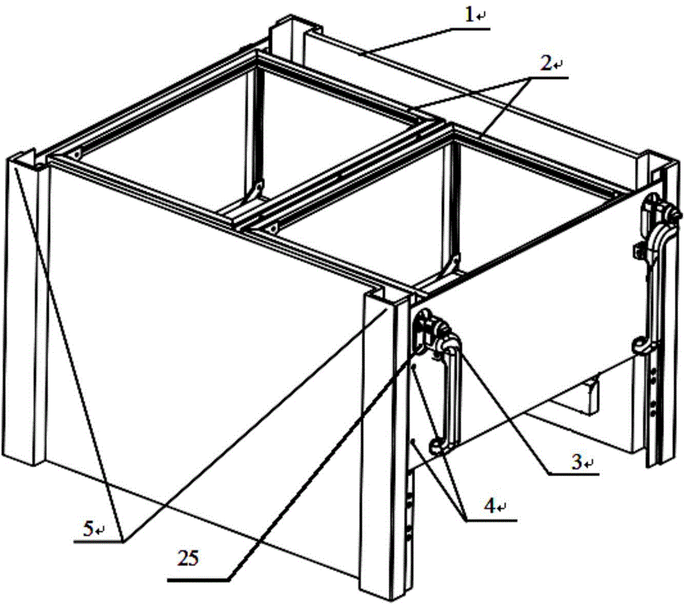
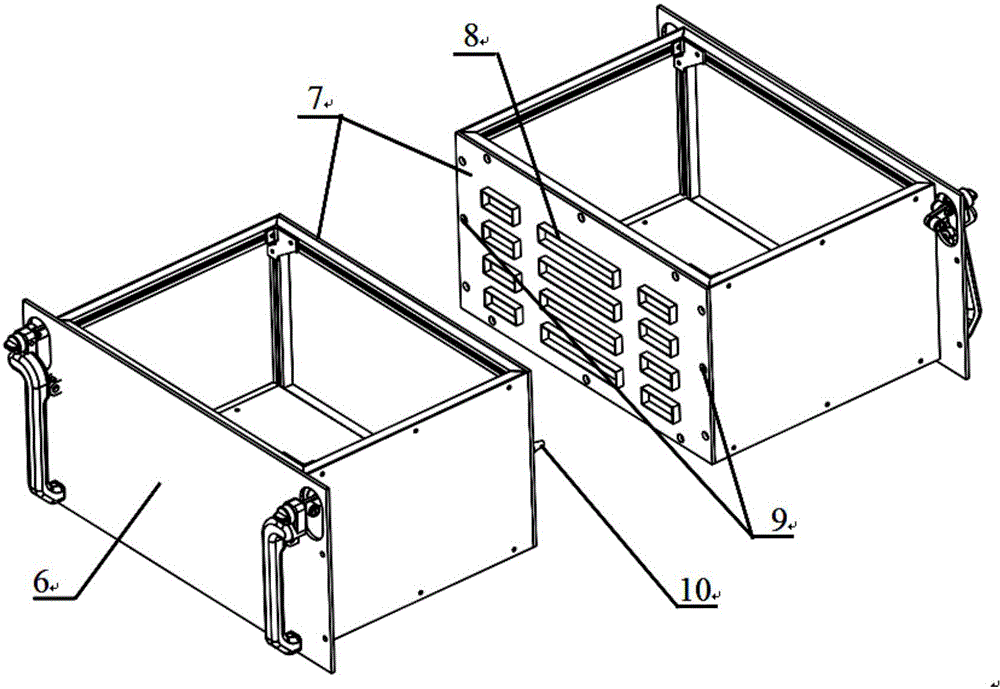
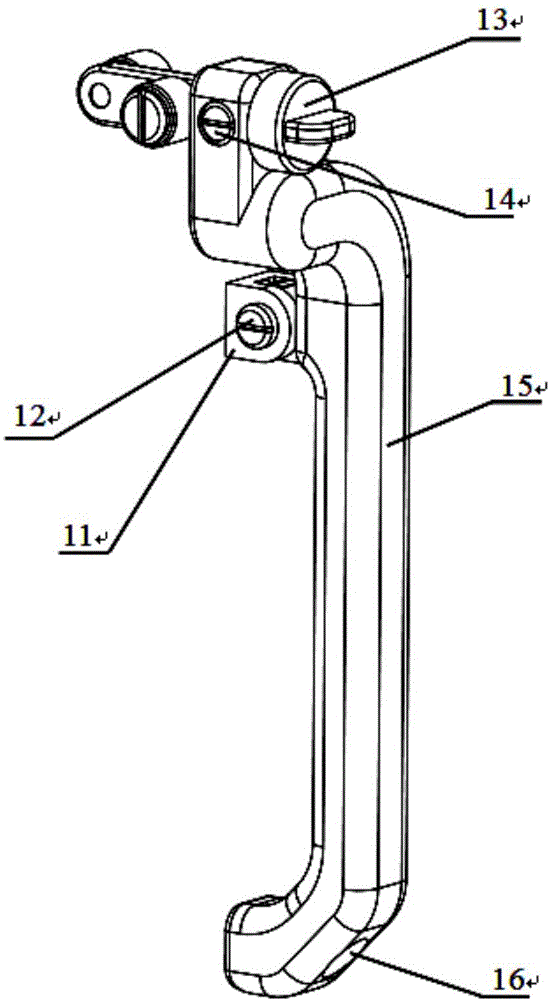
[0032] Such as figure 1 , 2 , 3, and 4, the present invention provides a multi-pin interface control cabinet chassis blind plug-in power-assisted handle mechanism, including a left-side plug-in and pull-out handle mechanism 3 symmetrically installed at both ends of the front panel 6 of the multi-pin interface chassis and the right side plug-and-pull handle mechanism 17, a control cabinet 1 is installed outside the front panel 6 of the multi-pin interface cabinet, and the control cabinet 1 is provided with a vertical beam 5 of the control cabinet at a position in contact with the front panel 6 of the multi-pin interface cabinet, wherein, The structure of the left-hand plug-and-extraction-assisting handle mechanism is the same as that of the right-side plug-and-extraction-assisted handle mechanism 17 , and the left-side plug-and-extraction-assisting handle mechanism i...


PUM


Abstract

The invention provides a blind plug type assisting handle mechanism for multi-pin type port control cabinet cases. The blind plug type assisting handle mechanism comprises plugging assisting handle mechanisms, wherein the plugging assisting handle mechanisms are of the same structure and are symmetrically installed on front panels of the multi-pin type port control cabinet cases. Each plugging assisting handle mechanism comprises a handle, a rotary knob assembly and a rotary knob fixing dowel. The handles are connected to the front panels of the multi-pin type port control cabinet cases in a rotating mode, the front panels of the multi-pin type port control cabinet cases are provided with through holes, and the through holes correspond to vertical beams of control cabinets arranged on the multi-pin type port control cabinet cases. One ends of the rotary knob assemblies are installed at the upper ends of the handles, the other ends of the rotary knob assemblies penetrate through the through holes to be arranged in the vertical beams of the control cabinets, and rotary knob fixing dowel hole sites are reserved in the rotary knob assemblies. Handle fixing dowel hole sites matched with the rotary knob fixing dowel hole sites are reserved in the upper ends of the handles. The rotary knob fixing dowels penetrate through the handle fixing dowel hole sites and the rotary knob fixing dowel hole sites to fix the handles and the rotary knob assemblies. Thus, blind plugging and pulling with assistance are achieved, the manual effect is reduced, and the installation performance and the maintenance performance of a measurement and control circuit module are improved.

Description

technical field [0001] The invention relates to the field of measurement and control and communication equipment, in particular to a multi-pin interface control cabinet chassis blind plug-in power-assisted handle mechanism. Background technique [0002] The components in the measurement and control equipment and communication equipment often adopt the rear panel assembly structure. Due to the large number of connectors in this structure, the cables in the chassis / cabinet are dense and messy, and it is difficult to maintain; to solve this problem, use between two chassis The rear panel is directly plugged and assembled. This structure can cancel the interconnection line between the upper and lower measurement and control units; and can effectively shorten the routing distance of the signal and power interconnection lines, which can greatly improve the reliability of the signal and power supply. [0003] At present, the number of interconnecting pins on the connectors on the r...

Claims


Application Information

Patent Timeline
IPC IPC(8): H05K7/02H05K7/10H05K7/12
Inventor 刘琼曹蕾蕾张涛惠记庄杨延璞陈疆
Owner CHANGAN UNIV
Why Eureka
Try Eureka