Machine frame for high-pressure roller press

A high-pressure roller and frame technology, used in presses, presses using rotating pressure components, grain processing, etc., can solve problems such as no function, high space requirements for bridge frames, etc., and achieve the effect of avoiding breaking points

Active Publication Date: 2014-08-13
KHD HUMBOLDT WEDAG GMBH
View PDF8 Cites 0 Cited by
  • Summary
  • Abstract
  • Description
  • Claims
  • Application Information

AI Technical Summary

Problems solved by technology

[0003] The disadvantage of this essentially successful construction is that the bridge frame has a high space requirement and is hardly functional in the use of high-pressure roller presses

Method used


Image

  • Machine frame for high-pressure roller press
  • Machine frame for high-pressure roller press
  • Machine frame for high-pressure roller press

Examples


Embodiment Construction

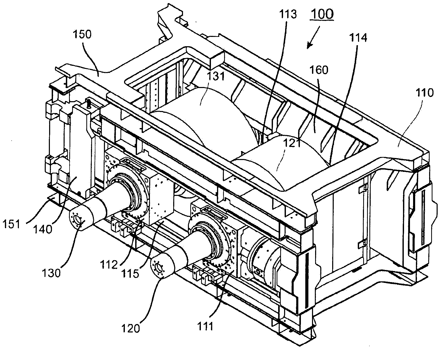
[0013] exist figure 1 A high-pressure roller press 100 with a stand 110 according to the invention is depicted in FIG. Bearing brackets 111 , 112 , 113 and (not visible) 114 sliding on mounts are accommodated in frame 110 , only the front mount 115 is visible in this view. A corresponding bearing is received in each bearing bracket, each bearing rotatably supporting the shafts 120 and 130 of the grinding rollers 121 and 131 .

[0014] In order to remove the grinding rollers 121 and 131 from the frame 110, it is provided in this design that the locking device 140 is taken out of the frame 110 in order to thereby open the machine on the side of the frame pointing backwards from the paper. shelf. The grinding rollers 121 and 131 with their bearings and bearing brackets 111, 112, 113 and 114 are then pushed out of the frame backwards with respect to the paper. The sub-elements or belt structures 150 and 151 remain after the grinding roller has been dismantled and form open open...


PUM


Abstract

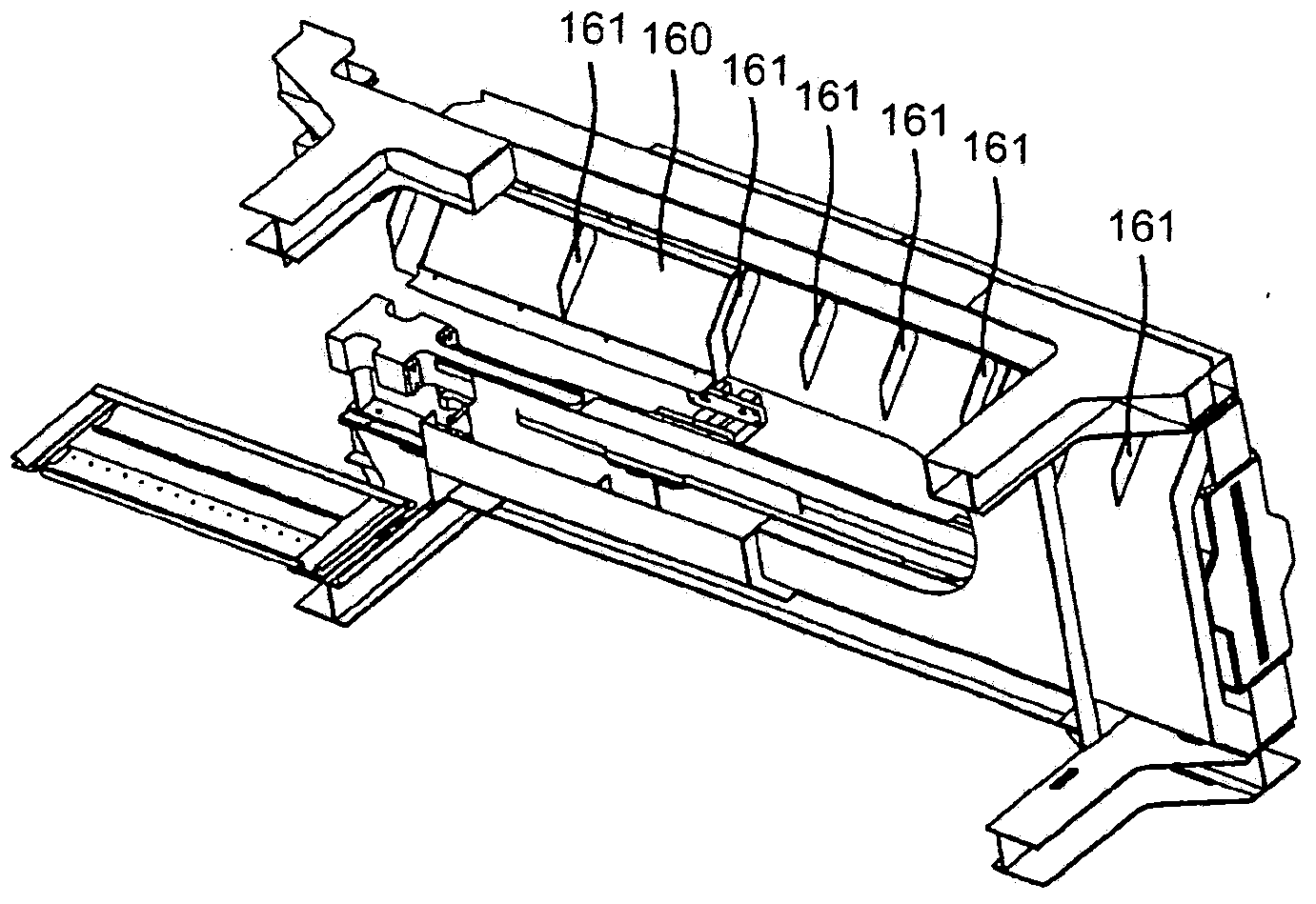
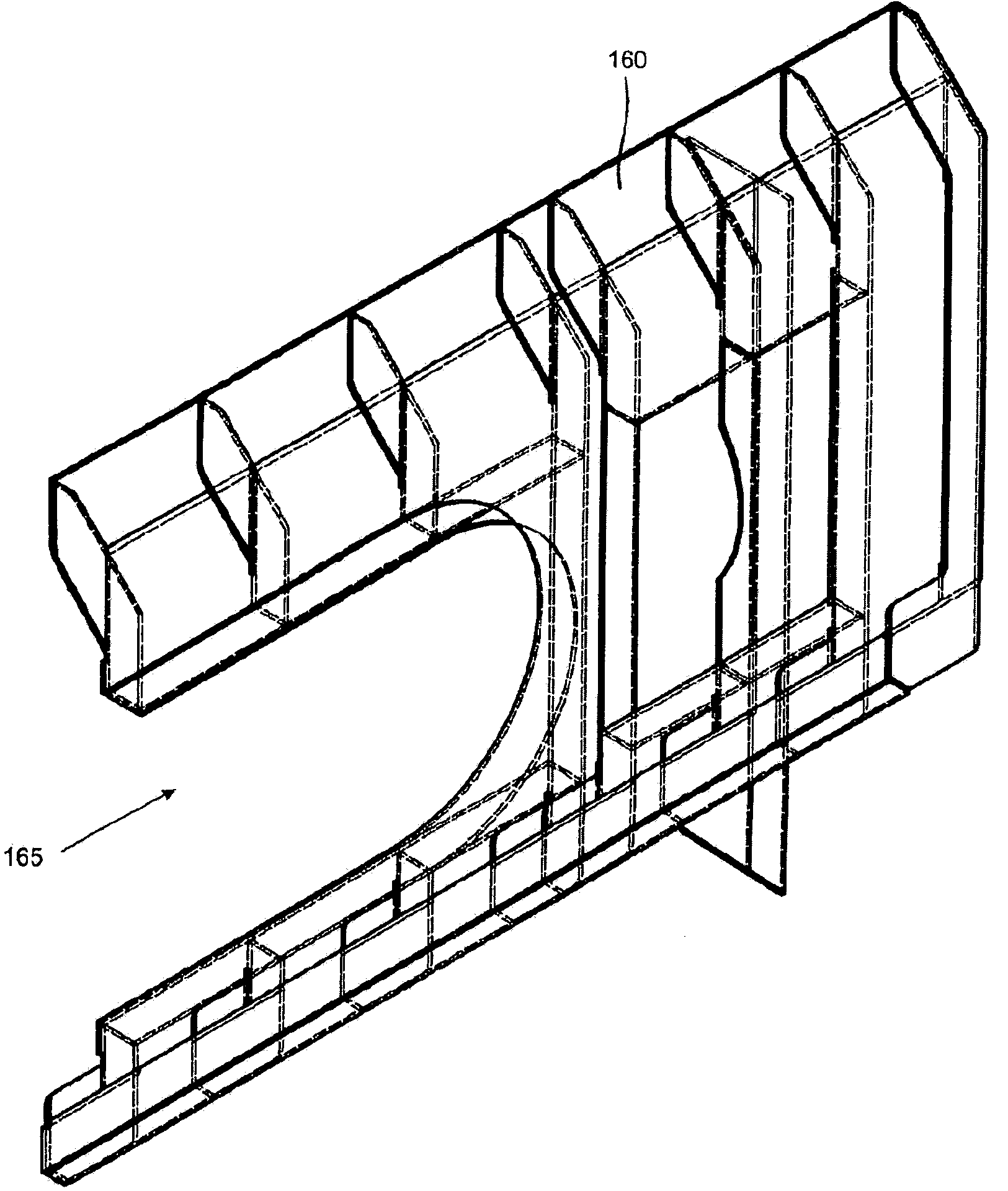
The invention relates to a machine frame (110) for a high-pressure roller press (100) which can be opened for disassembly. According to the suggestions of the invention, opposing belts (150, 151) in the machine frame (110) are connected by a side wall (160). Because of the side wall, bridge supports for stabilizing the machine frame during disassembly are not required.

Description

technical field [0001] The invention relates to a frame for a high-pressure roller press, which frame can be opened for disassembly. Background technique [0002] The high-pressure roller press for comminuting the material to be ground is for the first time etc. are disclosed in German publication DE2708053A1. High-pressure roller presses comminute the material to be ground between two counter-rotating rolls, by introducing the material to be ground into a narrow roll gap between the two rolls, which do not exhibit slippage. In the roller gap the material to be ground is not crushed energy-consumingly by shearing, but only by pressure loads. Despite the absence of shearing, the rolls used in high pressure rolling presses are still subject to very high wear, so the rolls are usually reprocessed or replaced. In order to simplify the dismantling of the high-pressure roller press when removing the rollers, it is proposed in DE 10 2005 045 273 A1 to design the frame in such a...

Claims


Application Information

Patent Timeline
Patent Type & Authority Applications(China)
IPC IPC(8): B02C4/02B02C4/28B30B3/04B30B15/04
CPCB02C4/02B02C4/28B30B3/04
Inventor M·弗兰根贝格
Owner KHD HUMBOLDT WEDAG GMBH
Why Eureka
Try Eureka