

Steering hanger assembly for vehicle
A hanger and vehicle technology, applied to the steering control, steering column, vehicle parts, etc. installed on the vehicle, to achieve the effect of suppressing the increase in weight, suppressing the increase in body weight, and improving the degree of freedom of configuration
- Summary
- Abstract
- Description
- Claims
- Application Information
AI Technical Summary
Problems solved by technology
Method used
Image

Examples
Embodiment 1
[0104] Regarding the vehicle steering hanger assembly of Example 1, based on Figure 1 to Figure 9 Be explained.
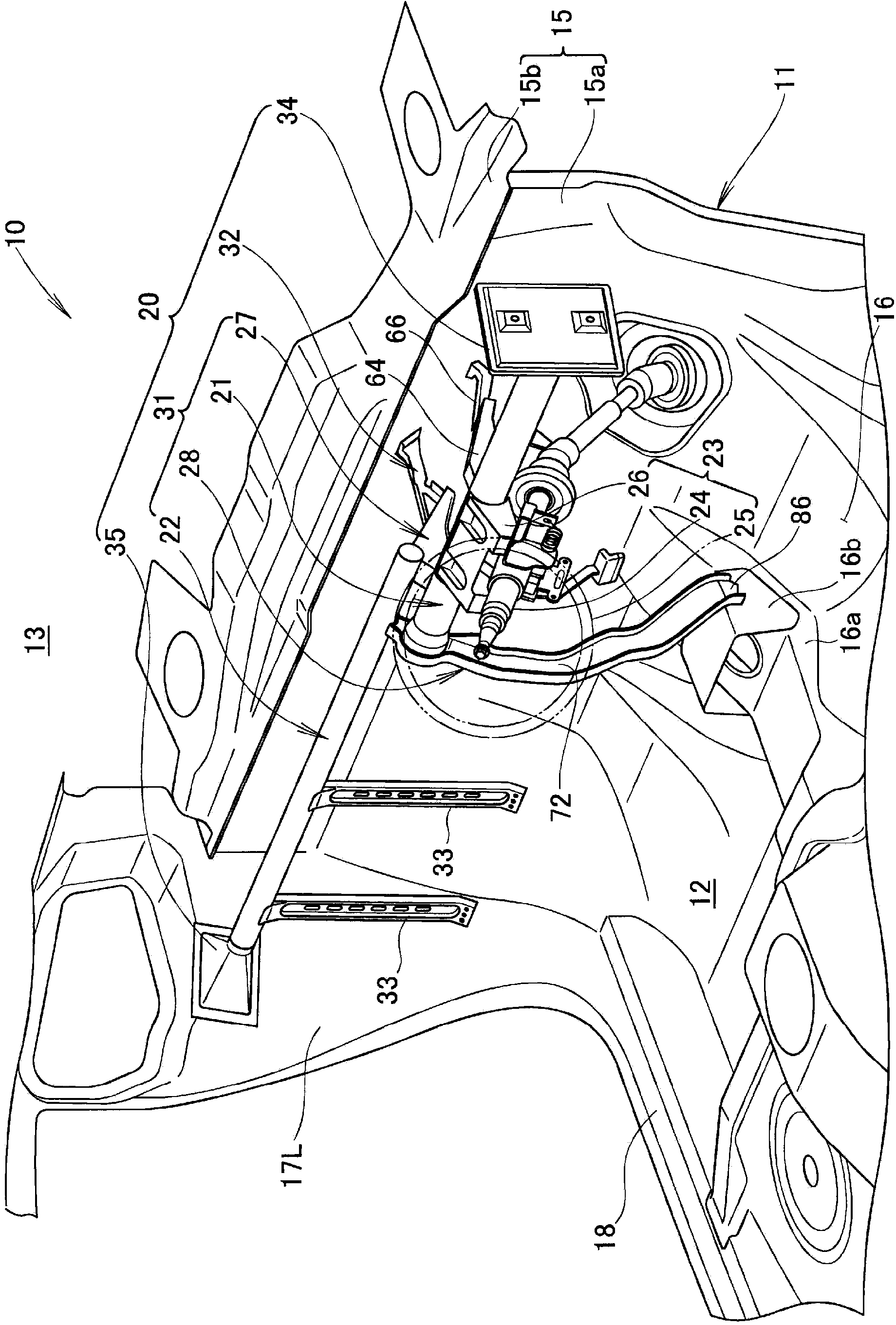
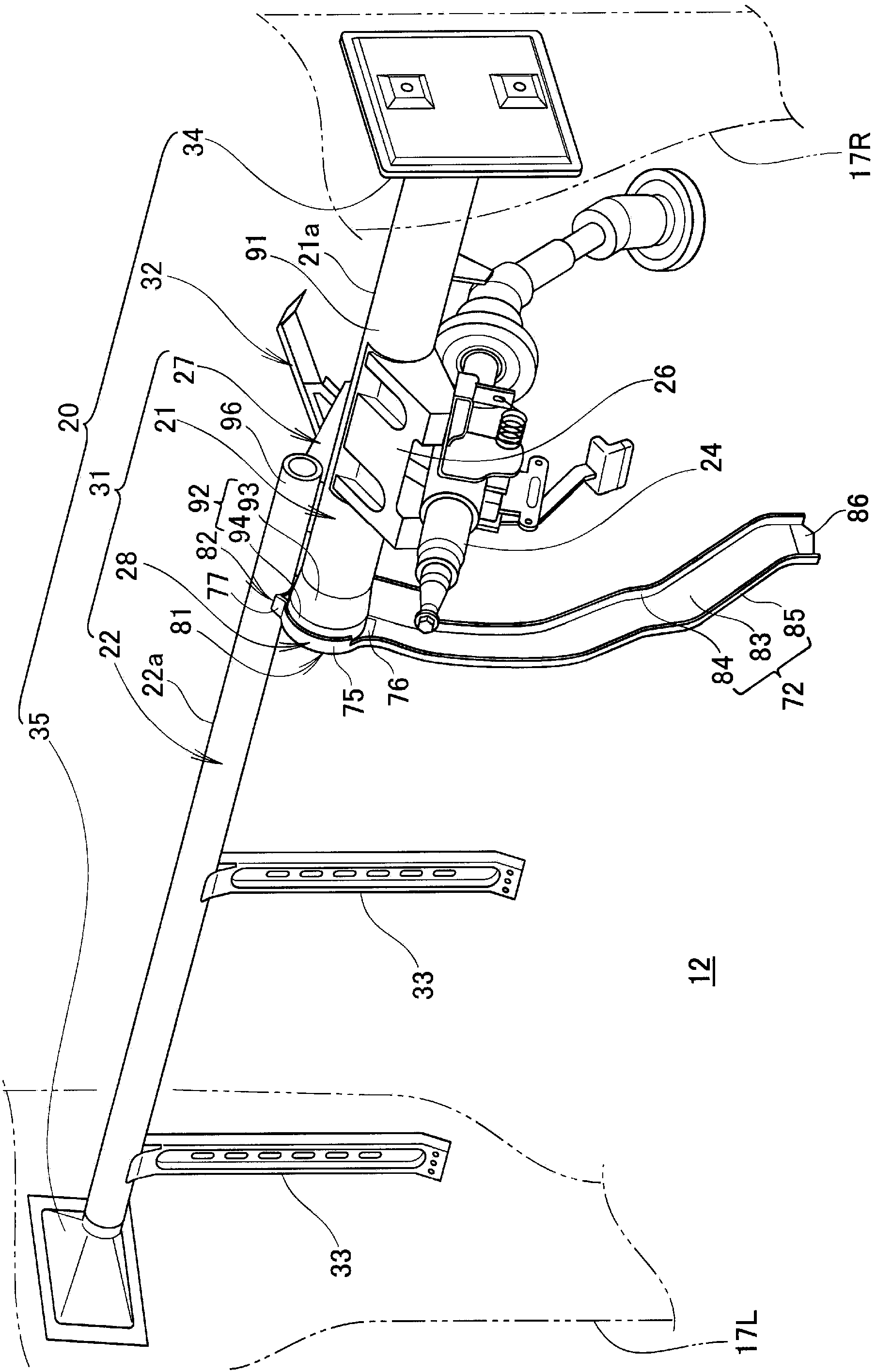
[0105] Such as figure 1 As shown, the vehicle 10 is, for example, a passenger car, and a front engine compartment 13 and a vehicle compartment 12 located directly behind the engine compartment 13 are formed on the inside of the vehicle body 11. The vehicle body 11 is composed of a monocoque vehicle body and is formed in a substantially bilaterally symmetrical shape. Such as figure 1 and figure 2 As shown, the front part of the vehicle body 11 includes an instrument panel 15, a floor 16, left and right front pillars 17L, 17R, and left and right side members 18 (only the left side is shown).
[0106] The instrument panel 15 is a member that partitions the vehicle compartment 12 and the engine compartment 13, and is composed of an instrument panel lower panel 15a on the lower side and an instrument panel panel 15b on the upper side. The floor 16 extends from the lower e...
Embodiment 2
[0147] Regarding the vehicle steering hanger assembly of Example 2, based on Figure 10 to Figure 12 Be explained. Picture 10 With the above Image 6 correspond. Picture 12 With the above Picture 9 correspond.
[0148] The vehicle steering hanger assembly 100 of the second embodiment is characterized in that the above Image 6 , Figure 7 and Picture 9 The left beam connecting member 28 of the illustrated embodiment 1 is changed to Figure 10 to Figure 12 The left beam connecting member 108 shown is similar to the above-mentioned Figure 1 to Figure 9 The structure shown is the same, so the description is omitted.
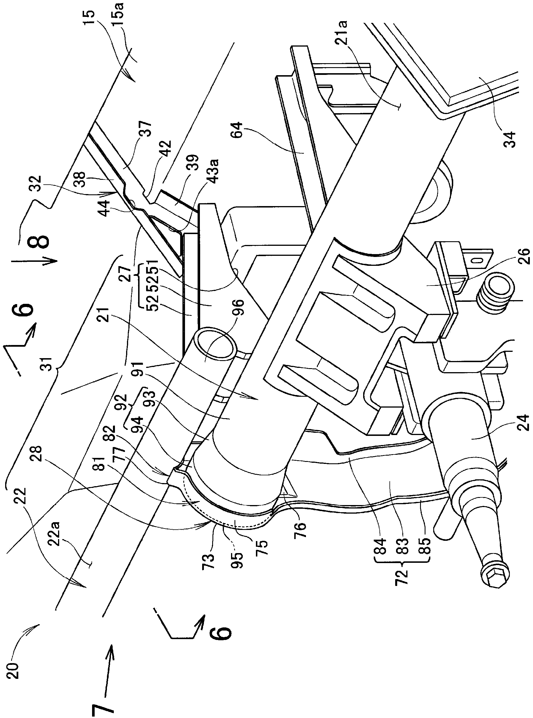
[0149] This left cross-member connection member 108 is a member that connects the mutually overlapping front end portions of the first and second cross-members 21 and 22, similarly to the left-beam connection member 28 of the first embodiment. This left beam connecting member 108 is appropriately referred to as "second bracket 108". The second vehicle body connectin...
Embodiment 3
[0162] Regarding the vehicle steering hanger assembly of Example 3, based on Figure 13 and Figure 14 Be explained. Figure 13 With the above Image 6 correspond. Figure 14 With the above Picture 9 correspond.
[0163] The vehicle steering hanger assembly 130 of the third embodiment is characterized in that the above Image 6 , Figure 7 and Picture 9 The left beam connecting member 28 of the illustrated embodiment 1 is changed to Figure 13 and Figure 14 The left cross beam connecting member 138 shown is similar to the above-mentioned Figure 1 to Figure 9 The structure shown is the same, so the description is omitted.
[0164] This left beam connecting member 138, like the left beam connecting member 28 of the first embodiment, is a member that connects the overlapping front end portions of the first and second beams 21 and 22 to each other. This left beam connecting member 138 is appropriately referred to as "second bracket 138".
[0165] With respect to the left cross member...
PUM
 Abstract
Description
Claims
Application Information