Synthetic resin cap for carbonated beverage-filled container, closure device, and beverage-filled closure device

A technology of carbonated beverages and synthetic resins, applied to bottle/container caps, capping containers with caps, applications, etc., can solve the problems of reduced sealing performance, easy to change, and reduced airtightness of the outer sealing protrusion 44, etc., to prevent Internal deformation, prevention of deterioration of sealing performance, effect of preventing deterioration of sealing performance

Inactive Publication Date: 2014-08-13
希赛瓶盖系统日本有限公司
View PDF7 Cites 4 Cited by
  • Summary
  • Abstract
  • Description
  • Claims
  • Application Information

AI Technical Summary

Problems solved by technology

[0011] However, the size (inner diameter, outer diameter, etc.) of the mouth 21 of the container 20 often changes due to changes in the ambient temperature, which affects the sealing performance of the caps 31 and 51.
In addition, when an impact from the outside is applied, the sealing performance of the outer sealing protrusion 44 is lowered, and the sealing performance is lowered.
[0012] In addition, in general, lubricating materials (erucamide, etc.) are added to the caps 31 and 51 for the p

Method used


Image

  • Synthetic resin cap for carbonated beverage-filled container, closure device, and beverage-filled closure device
  • Synthetic resin cap for carbonated beverage-filled container, closure device, and beverage-filled closure device
  • Synthetic resin cap for carbonated beverage-filled container, closure device, and beverage-filled closure device

Examples


Example Embodiment

[0120] (Example 1)

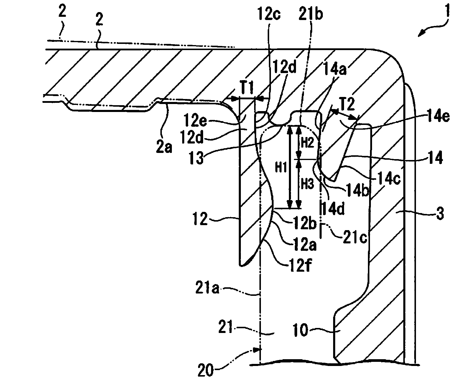
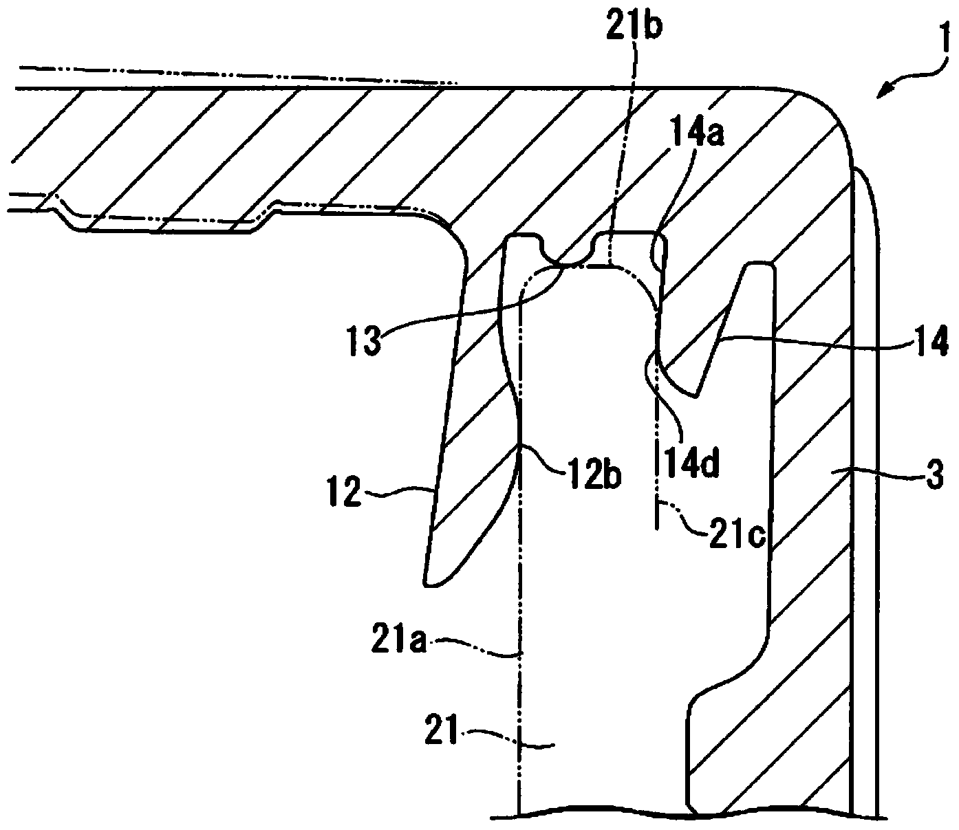
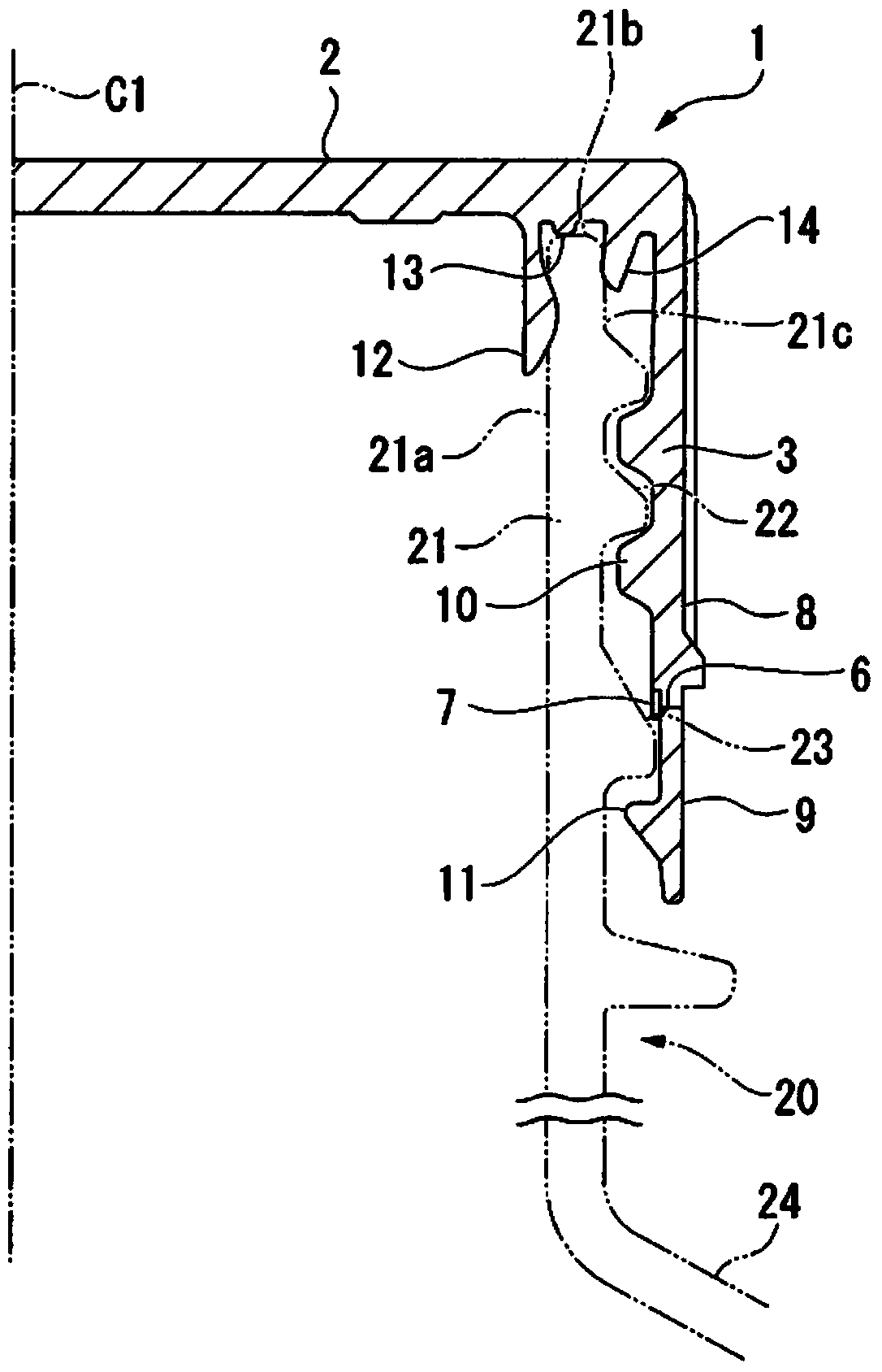
[0121] make Figure 1A Cover 1 shown. The cover 1 is made of high-density polyethylene, and no lubricating material is used. The cap 1 was attached to the mouth 21 of the container 20, and the closure was used for a heat cycle test. The ratio (Fo:Fi) of the inward pressing force Fo of the outer sealing protrusion 14 with respect to the outer surface 21c to the outer pressing force Fi of the inner sealing protrusion 12 with respect to the inner surface 21a is 1.5:1.

[0122] In the thermal cycle test, the process of leaving the container 20 and the lid 1 under heating conditions (55° C.) for 9 hours and then under cooling conditions (22° C.) for 15 hours was repeated twice. Then, the container 20 and the lid 1 were placed Cover 1 was left for 24 hours under the condition of 5°C.

[0123] image 3 The results of measuring the outer diameter of the mouth portion 21 of the container 20 before and after the heat cycle test are shown. image 3 The abscissa...

Example Embodiment

[0129] (Example 2)

[0130] The curling angle of the same cap 1 as in Example 1 was measured. The number of samples is 25. Figure 5 Indicates the distribution of curling angles. Figure 5 The horizontal axis of is the curling angle, and the vertical axis is the number of samples.

[0131] The curling angle refers to the rotation angle of the cap 1 when the cap 1 is attached to the mouth 21 with a predetermined torque.

[0132] After the cap 1 was manufactured, it was left to stand at room temperature for three days, and then the curling angle was measured at room temperature.

Example Embodiment

[0133] (Example 3)

[0134] After producing the same cap 1 as in Example 1, it was left to stand at room temperature for three days, then left to stand under heating (55° C.) for 24 hours, and then the curling angle of the cap 1 was measured at room temperature. Other conditions are the same as in Example 2. Figure 5 Indicates the result.


PUM

PropertyMeasurementUnit
The average thicknessaaaaaaaaaa

Abstract

The present invention provides a synthetic resin cap fitted on the mouth section of a container filled with a carbonated beverage. The cap is provided with a top plate and a cylindrical section extending down from the rim thereof. On the inner surface of the top plate, a ring-shaped inner seal projection that is fitted inside the mouth section and an outer seal projection that abuts the outer surface of the mouth section are formed. On the outer surface of the inner seal projection, a ring-shaped contacting protrusion that contacts the inner surface of the mouth section is formed. The outer seal projection has an inner surface, the internal diameter of which decreases towards the leading edge, and the smallest internal diameter section, which is the lower end of the inner surface, contacts the outer surface of the mouth section at a position that is towards the container body side and is at a distance from the open end.

Description

technical field [0001] The present invention relates to a synthetic resin cap for closing the mouth of a container, a closing device using the synthetic resin cap, and a closing device for filling beverages. The closing device of the synthetic resin cap and the closing device of the filled beverage. [0002] this application claims priority based on Japanese Patent Application No. 2011-253824 for which it applied in Japan on November 21, 2011, and uses the content here. Background technique [0003] As a synthetic resin cap (hereinafter, simply referred to as a cap) for a container filled with carbonated beverages, there is a cap having a top and a cylindrical portion hanging down from the periphery of the top, and a threaded portion is formed on the inner surface of the cylindrical portion ( For example, refer to Patent Document 1). [0004] Image 6 An example of a cap, the cap 31 includes a top 32 and a cylindrical portion 33 hanging from the periphery of the top, and a...

Claims


Application Information

Patent Timeline
IPC IPC(8): B65D41/04
CPCB65D41/325B65D41/3447B65D41/0421B65D41/0428B65D41/04
Inventor 都筑光夫高泽史宪山本祥司
Owner 希赛瓶盖系统日本有限公司
Why Eureka
Try Eureka