Wafer cleaning machine

A cleaning machine and strip technology, applied in the field of cleaning machines, can solve the problems of low automation, unclean cleaning and difficult separation of wafers, etc., and achieve the effects of reducing labor costs, improving product yield, and improving production efficiency

Active Publication Date: 2014-08-20
CHENGDU TIMEMAKER CRYSTAL TECH
View PDF7 Cites 6 Cited by
  • Summary
  • Abstract
  • Description
  • Claims
  • Application Information

AI Technical Summary

Problems solved by technology

[0005] At present, the wafer cleaning process is to put the wafer into the cleaning basket, throw it up and down in a single-slot ultrasonic machine, and then go through 4 single-slot cleanings to complete the final cleaning work. However, the cleaning basket is thrown up and down for cleaning, and the wafers are stacked At the same time, it is difficult to separate, the wafer cleaning is not clean, the throwing cleaning and the movement between different tanks need manual work, and the degree of automation is not high

Method used


Image

  • Wafer cleaning machine
  • Wafer cleaning machine
  • Wafer cleaning machine

Examples


Embodiment Construction

[0022] The present invention will be further described below in conjunction with accompanying drawing, protection scope of the present invention is not limited to the following:

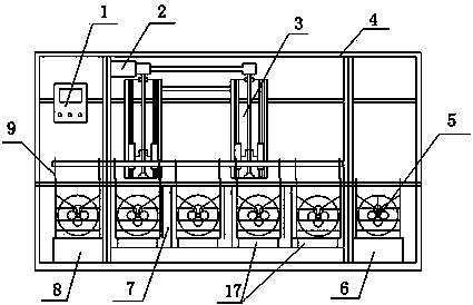
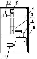
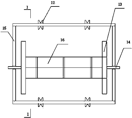
[0023] like figure 1 and figure 2 As shown, a strip cleaning machine includes a frame 4, and the lower part of the frame 4 is sequentially provided with a loading table 6, a cleaning tank 7, a blanking table 8 and a driving device from right to left, The bottom of the cleaning tank 7 is provided with an ultrasonic vibrating plate 17, the cleaning tank 7 is provided with a rotary cleaning device 5, and the rotary cleaning device 5 is driven to rotate by a driving device. Hook manipulator 3, the deceleration motor B10 that drives single-arm multi-hook manipulator 3 to move horizontally and the deceleration motor C2 that drives single-arm multi-hook manipulator 3 to move up and down, in the present embodiment, deceleration motor B10, deceleration motor C2 and deceleration motor A11 are erected on On ...


PUM


Abstract

The invention discloses a wafer cleaning machine which comprises a rack (4). A feeding workbench (6), a cleaning tank (7) and a discharging workbench (8) are arranged on the lower portion of the rack (4) from right to left in sequence, an ultrasonic vibrating plate (17) is arranged at the bottom of the cleaning tank (7), a rotary cleaning device (5) is arranged in the cleaning tank (7), a single-arm multi-hook mechanical arm (3), a gear motor B (10) driving the single-arm multi-hook mechanical arm (3) to horizontally move and a gear motor C (2) driving the single-arm multi-hook mechanical arm (3) to vertically move are arranged on the upper portion of the rack (4), a plurality of hooks (9) are arranged on an arm body of the single-arm multi-hook mechanical arm (3) and are used for lifting the rotary cleaning device (5), and a controller (1) is further arranged on the rack (4). The wafer cleaning machine has the advantages of being high in automation degree, high in product yield, high in product quality and low in manpower cost.

Description

technical field [0001] The invention relates to a cleaning machine, in particular to a strip cleaning machine. Background technique [0002] In production and life, there are many things that need to be cleaned, and there are many types and links that need to be cleaned. Therefore, in order to cope with the many things that need to be cleaned, a variety of cleaning equipment has appeared in the society, and a variety of cleaning processes have been adopted, such as dipping, brushing, pressure washing, vibration cleaning and steam cleaning, etc., but when faced with The surface of the items to be cleaned is relatively complex, such as some mechanical parts with uneven surfaces and blind holes, and some products that are particularly small and have high requirements for cleanliness, such as: clocks and precision machinery parts, electronic components, circuits Board components, etc.; conventional cleaning methods can no longer meet the requirements, even steam cleaning and hi...

Claims


Application Information

Patent Timeline
IPC IPC(8): B08B3/10B08B3/12B08B13/00
CPCB08B3/044B08B3/045B08B3/123
Inventor 叶竹之石清
Owner CHENGDU TIMEMAKER CRYSTAL TECH
Why Eureka
Try Eureka