Method for milling end surface of large-cross-section steel component

A processing method and large-section technology, applied in metal processing equipment, milling cutters, manufacturing tools, etc., can solve the problems of short cantilever, large end milling line error, poor accuracy, etc., to achieve a simple and clear method, reduce end milling Line error, the effect of improving accuracy and efficiency

Inactive Publication Date: 2014-08-20
MCC TIANGONG GROUP
View PDF4 Cites 3 Cited by
  • Summary
  • Abstract
  • Description
  • Claims
  • Application Information

AI Technical Summary

Problems solved by technology

For the end milling of large cross-section steel members, after the end milling line is determined perpendicular to the central axis at the larger surface, the crane is used to adjust the movement of the crowbar or the cantilever tooling made by the manufacturer is fixed and adjusted, and then the end mill is unloaded. The method of face milling after adjusting the coincidence of the end mill head trajectory and the end milling line after observing the operation of the end milling surface. This method has the following problems and shortcomings in practical application: 1. The end milling line determined perpendicular to the central axis The error is large and cannot be checked; 2. The crane cooperates with the movement of the crowbar to adjust the fixed component with low efficiency and poor accuracy; 3. The cantilever tooling made by the manufacturer generally has a short cantilever, which cannot meet the needs of fixing large cross-section components; 4 , Due to the presence of milling chips during end milling, the observation of the coincidence of the end mill running track and the end mill line is not clear
Due to the existence of the above problems, this method can only be applied to the end face milling of ordinary steel components that do not require high precision, and the deviation increases with the increase of the cross section. Either a lot of time is invested in repeated review and adjustment to meet the accuracy requirements, or secondary processing occurs during installation because it cannot meet the installation requirements, resulting in cost waste and low efficiency.

Method used


Image

  • Method for milling end surface of large-cross-section steel component
  • Method for milling end surface of large-cross-section steel component
  • Method for milling end surface of large-cross-section steel component

Examples


Embodiment Construction

[0019] The present invention will be further described in detail below through the specific examples, the following examples are only descriptive, not restrictive, and cannot limit the protection scope of the present invention with this.

[0020] A method for end face milling of large cross-section steel components, characterized in that: the steps of the method are:

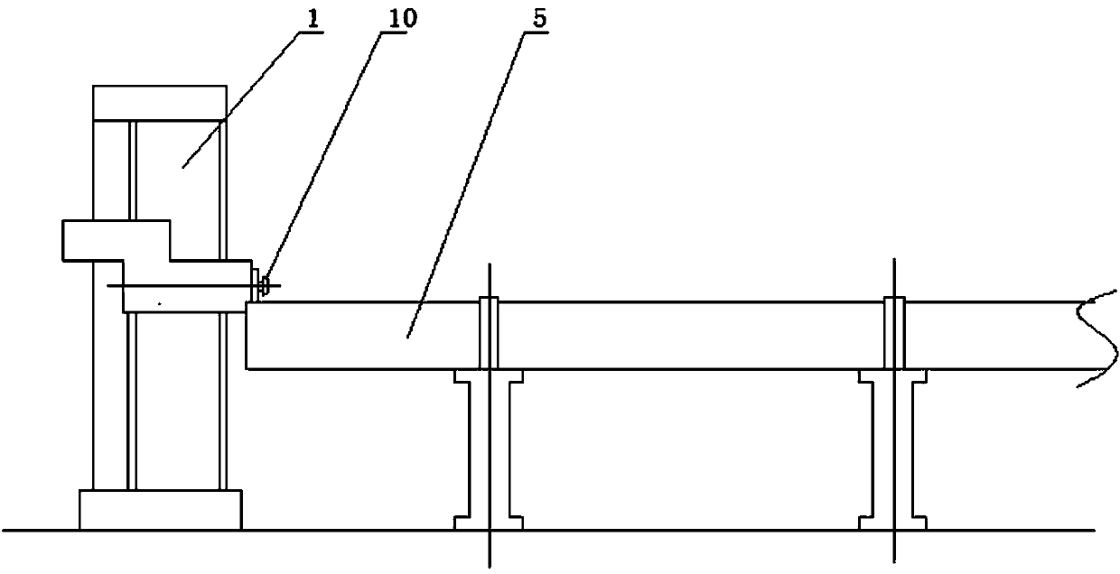
[0021] ⑴. First, correct the fabricated large-section steel member 5 to ensure that the dimensions of each member are within the allowable deviation range;

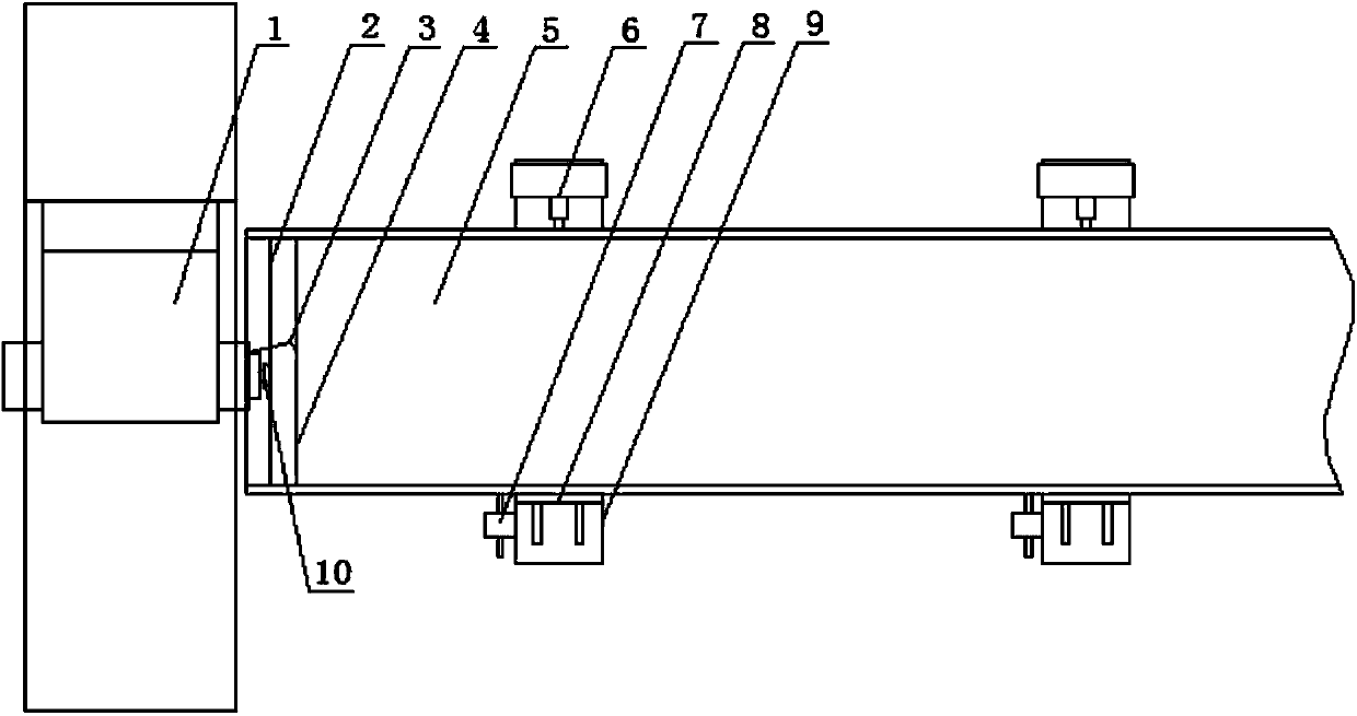
[0022] (2) Draw end milling line 2 and end milling observation line 4: use right-angle Pythagorean method to draw end milling line and end milling observation line on the wide surface of large cross-section steel members;

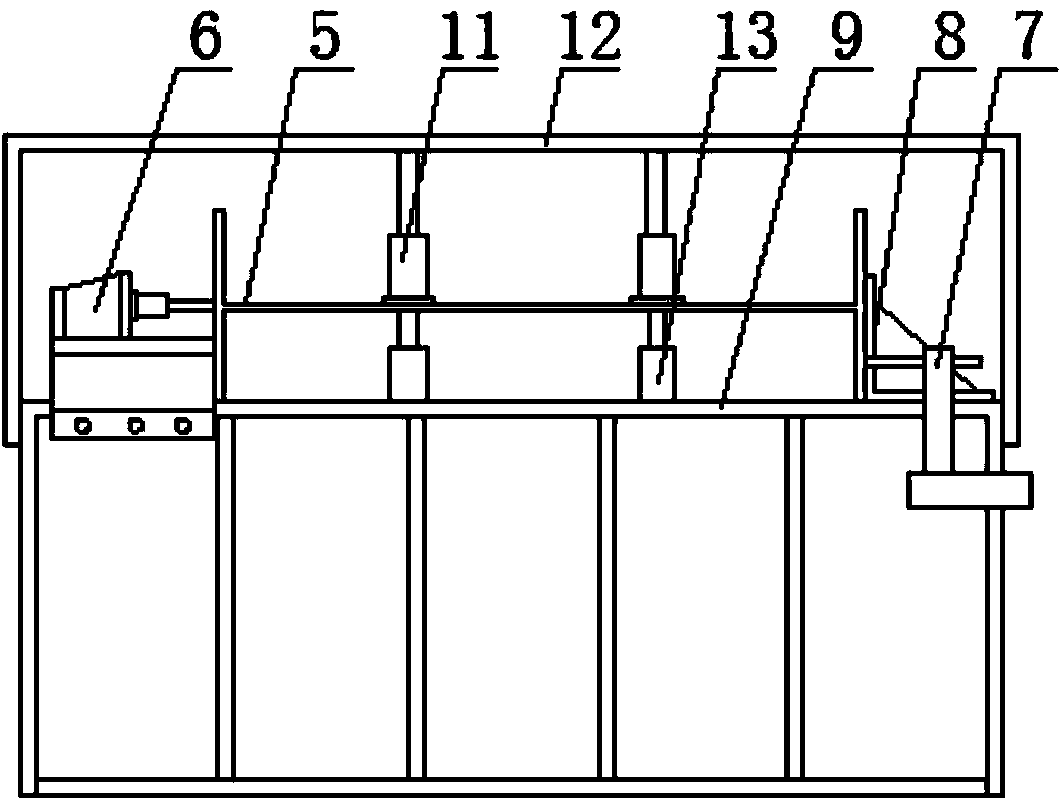
[0023] ⑶. Longitudinal and transverse initial adjustment of the placement position of large-section steel components: Hoist the large-section steel components on the support plane reference tire 9 of the clamping and fixing tooling. When...


PUM


Abstract

The invention relates to a method for milling an end surface of a large-cross-section steel component. The method comprises the following steps: (1) calibrating a manufactured large-cross-section steel component to ensure that each size of the component is within an allowable deviation range; (2) scribing an end milling line and an end milling observation line; (3) primarily adjusting the longitudinal direction and the transverse direction of the placement position of the large-cross-section steel component; (4) performing fine adjustment on the consistency of an end milling cutter running track and the end milling line of the large-cross-section steel component; (5) fixing the large-cross-section steel component; (6) performing end milling. The method for milling the end surface of the large-cross-section steel component disclosed by the invention is easy to operate; the error of the end milling line is effectively reduced by precise calibration; the end surface milling precision and the end surface milling efficiency are greatly improved by the methods of precisely scribing the end milling line and the end milling observation line, performing fine adjustment on a clamping tool fixing component of the component, performing component end milling track tracking by a machine scribing needle frame and the like, and the cost is reduced greatly.

Description

technical field [0001] The invention belongs to the field of end milling of steel components, in particular to a method for end milling of large cross-section steel components. Background technique [0002] In the fabrication and processing of steel structural members with seamless top-tight connection, in order to ensure full contact of the end faces of the members and reliable force transmission, the specification stipulates that the processing method of end face milling shall be used for the end face treatment of the members. For the end milling of large cross-section steel members, after the end milling line is determined perpendicular to the central axis at the larger surface, the crane is used to adjust the movement of the crowbar or the cantilever tooling made by the manufacturer is fixed and adjusted, and then the end mill is unloaded. The method of face milling after adjusting the coincidence of the end mill head trajectory and the end milling line after observing t...

Claims


Application Information

Patent Timeline
Patent Type & Authority Applications(China)
IPC IPC(8): B23C5/00
Inventor 李显峰张育红张秀东
Owner MCC TIANGONG GROUP
Why Eureka
Try Eureka