
Circuit board splitting machine

A technology of circuit board and board splitting machine, which is applied in the direction of metal processing machinery parts, feeding devices, and attachments of shearing machines, etc. It can solve problems such as broken parts, rough incisions, and cracked solder joints, so as to prevent solder joints from cracking , Reduce stress and prevent parts from breaking

Inactive Publication Date: 2014-08-20
SUZHOU BECHENLAI ELECTRONICS
View PDF2 Cites 11 Cited by
  • Summary
  • Abstract
  • Description
  • Claims
  • Application Information

AI Technical Summary

Problems solved by technology

[0003] The purpose of the present invention is to overcome the deficiencies in the prior art, provide a circuit board splitter, and solve the technical problems in the prior art that the cuts of the circuit board are rough, the solder joints are cracked or the parts are broken due to the cutting stress.

Method used


Image

  • Circuit board splitting machine

Examples


Embodiment Construction

[0013] The present invention will be further described below in conjunction with the accompanying drawings. The following examples are only used to illustrate the technical solution of the present invention more clearly, but not to limit the protection scope of the present invention.

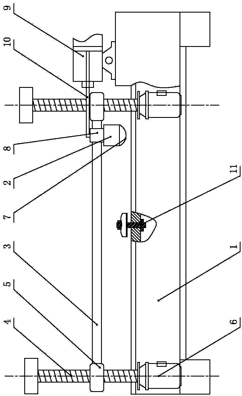
[0014] Such as figure 1 As shown, a circuit board splitting machine includes a cutting table 1 , a tool holder 2 and a guide rail 3 . The guide rail 3 is fixed on the cutting table 1 through a liftable support. The liftable support includes a screw 4 arranged on the left and right sides of the cutting table 1 and a nut seat 5 connected to the two ends of the guide rail 3. The nut seat 5 and the lead screw 4 are connected by threads. , the lower end of leading screw 4 is provided with respective driving motor 6, and driving motor 6 starts and drives leading screw 4 to rotate, thus drives nut seat 5 to run up and down, realizes the lifting of guide rail 3, and then realizes the lifting of blade 7...


PUM


Abstract

The invention discloses a circuit board splitting machine. The technical problems of coarse cuts and welding spot crazing or part breakage caused by cutting stress of a circuit board in the prior art is solved. The circuit board splitting machine comprises a cutting table, a tool rest and guide rails, wherein the guide rails are fixed on the cutting table through a liftable support. A blade for cutting the circuit board is arranged on the tool rest, the tool rest is in sliding connection with the guide rails through slide blocks, and a control device for controlling left-right walking of the tool rest along the guide rails is arranged on the cutting table. When the circuit board splitting machine works, a driving motor drives a lead screw to rotate and accordingly drives a nut seat to run vertically to achieve lifting of the guide rails and further achieve lifting and descending of the blade, and an air cylinder pushes the blade to walk in a left-right mode so as to achieve circuit board cutting. Compared with the prior art, the circuit board splitting machine has the advantages that feeding type advance cutting is adopted, the stress can be thoroughly decreased, smooth cuts can be ensured, and welding spot crazing and part breakage can be prevented; the tool rest can freely lift with the guide rails, the cutting depth is controllable, and cutting of different circuit boards in thickness is achieved.

Description

technical field [0001] The invention relates to a circuit board separating machine, which belongs to the technical field of circuit board production machinery. Background technique [0002] At present, there are two methods of PCB splitting: machine splitting and manual splitting. The cost of manual splitting is very low, and the operation is not complicated, but there are problems such as low production efficiency and rough and defective borders. There is a board splitting machine in the prior art, which includes a horizontal guide rail and a cutter. The cutter is arranged below the guide rail, and the cutter is vertically upward. The guide rail moves up and down relative to the cutter. The sliding assembly is movably connected with the guide rail, and the sliding assembly moves back and forth along the guide rail. . When in use, the cutter is located at the lower part of the plate to be cut, and the single wheel bearing of the sliding assembly presses the upper part of th...

Claims


Application Information

Patent Timeline
IPC IPC(8): B23D19/00B23D33/00B23Q5/40
Inventor 李勇孙敏强
Owner SUZHOU BECHENLAI ELECTRONICS
Learn More