

Vice
A vise and vise body technology, which is applied in the vise field, can solve the problems of inability to adjust the clamping direction, low work efficiency, and long time required to clamp the workpiece, so as to shorten the loading and unloading time, improve production efficiency, and have a simple structure Effect
- Summary
- Abstract
- Description
- Claims
- Application Information
AI Technical Summary
Problems solved by technology
Method used
Image

Examples
Embodiment
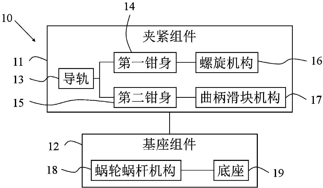
[0024] figure 1 is the block diagram of the vise.
[0025] Such as figure 1 As shown, the vise 10 includes a clamping assembly 11 and a base assembly 12 .
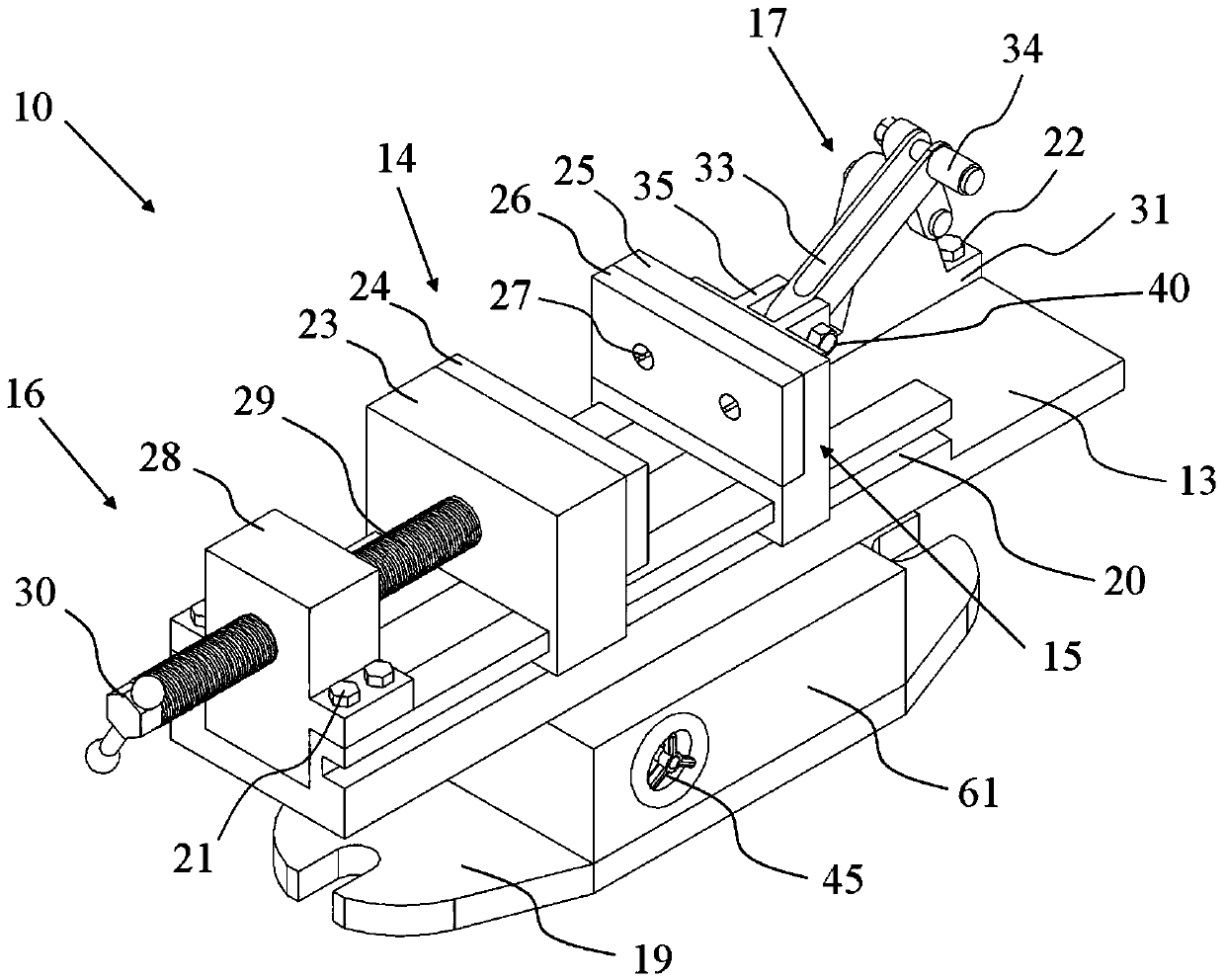
[0026] figure 2 Is the schematic diagram of the vise structure.
[0027] Such as figure 1 , 2 As shown, the clamping assembly 11 is used to clamp a workpiece (not shown in the figure). The clamping assembly 11 includes a guide rail 13 , a first clamp body 14 , a second clamp body 15 , a screw mechanism 16 , and a slider crank mechanism 17 .
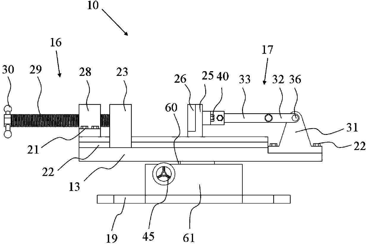
[0028] image 3 is the front view of the vise.
[0029] Such as figure 2 , 3 As shown, the guide rail 13 is installed on the base assembly 12, and the guide rail 13 is provided with a groove 20, and the lower ends of the first tong body 14 and the second tong body 15 are respectively installed in the groove 20 of the guide rail 13, and can be moved along the The groove 20 slides back and forth on the guide rail 13 . The screw mechanism 16 is installed on one end of the g...
PUM
 Abstract
Description
Claims
Application Information