Eureka AIR delivers breakthrough ideas for toughest innovation challenges, trusted by R&D personnel around the world.

Double-feeding vacuum fitting production line and fitting process thereof

A production line and vacuum technology, applied in the direction of layered products, lamination devices, lamination auxiliary operations, etc., can solve the problems of inability to meet the production capacity requirements of automated production lines, inability to flexibly adjust the position, and low lamination efficiency. Line production capacity, improve time utilization, and improve the effect of laminating efficiency

Pending Publication Date: 2019-02-19
SHENZHEN NUOFENG OPTOELECTRONICS EQUIP
View PDF4 Cites 2 Cited by
  • Summary
  • Abstract
  • Description
  • Claims
  • Application Information

AI Technical Summary

Problems solved by technology

The screen manufacturing process involves a film-attaching process. The film-attaching process realizes the attachment of various sheet-shaped films on the glass sheet. The sheet-shaped films include polarizers, TP films, etc.; Bubbles are easily generated between the sheet and the glass sheet, which affects the quality of the film; in view of this situation, a vacuum film process has appeared in the existing technical means. The air in the airtight environment is pumped out to form a vacuum environment. In the vacuum environment, the film is attached to the glass sheet, which can greatly reduce the occurrence of air bubbles when the film is attached; vacuum lamination mostly adopts the form of a stand-alone machine, and the process of automatic transformation and upgrading of the entire screen production line In the process of realizing the automation of vacuum film lamination, the following key technical problems need to be solved: 1. The traditional stand-alone vacuum lamination can only complete the lamination of a single product at a time, and the lamination efficiency is low, which cannot meet the production capacity requirements of the automated production line; 2. , The existing vacuum bonding method for glass film is to transport the film and glass sheet to the upper laminating chamber and the lower laminating chamber respectively, and the film and the glass sheet are bonded through the laminating upper chamber and the laminating lower chamber. After the film is fixed, the upper and lower chambers are vacuumed, and the upper and lower molds in the upper and lower chambers vacuum-fit the film and the glass sheet in the vacuum environment of the chamber; this kind of structural process requires special clamps in the upper and lower chambers. The mounting structure prevents the diaphragm or glass sheet from falling due to gravity or prevents the position of the diaphragm and glass sheet from shifting before laminating, and when the position of the clamped diaphragm or glass sheet is shifted, the position cannot be adjusted flexibly, which will directly lead to Mounting defective products requires very high positioning and clamping accuracy when feeding film or glass sheets, resulting in equipment manufacturing costs that are much higher than ordinary film laminating equipment, and the market value is not high; 3. The vacuum bonding device of a single machine is fully automated The production line is automatically connected with the front and back processes to shorten the material transfer time and improve the production capacity of the whole line; 4. During the vacuum lamination process, the previous station of the vacuum lamination station is constantly exporting materials, and the latter station is constantly exporting materials. The vacuum lamination station needs incoming materials for processing. Because the vacuum lamination process takes time, material transmission will stop during vacuum lamination, which greatly wastes processing time and is a key factor restricting the increase in production capacity of the entire line. one

Method used


Image

  • Double-feeding vacuum fitting production line and fitting process thereof
  • Double-feeding vacuum fitting production line and fitting process thereof
  • Double-feeding vacuum fitting production line and fitting process thereof

Examples


Embodiment Construction

[0044] The present invention will be further described below in conjunction with accompanying drawing:

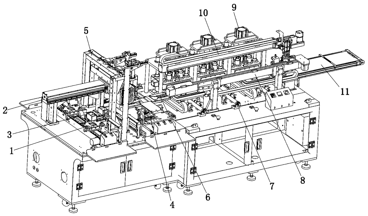
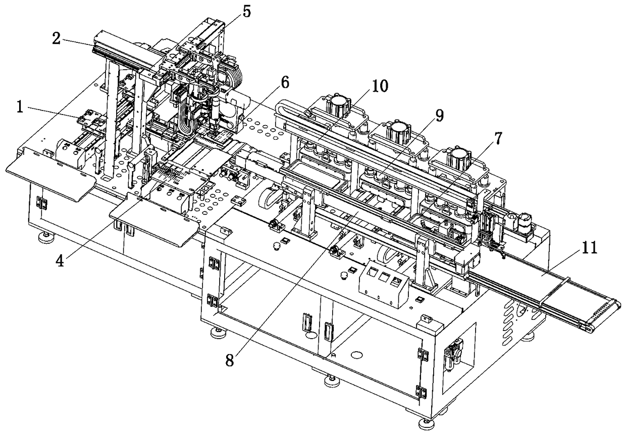
[0045] Such as Figure 1 to Figure 14 As shown, the technical scheme adopted by the present invention is as follows: a double-feeding vacuum lamination production line, including a pre-lamination part and a vacuum lamination part arranged side by side, and glass sheets and TP films are bonded together in the pre-lamination part The filmed glass sheet, the filmed glass sheet is vacuum bonded at the vacuum bonding part;

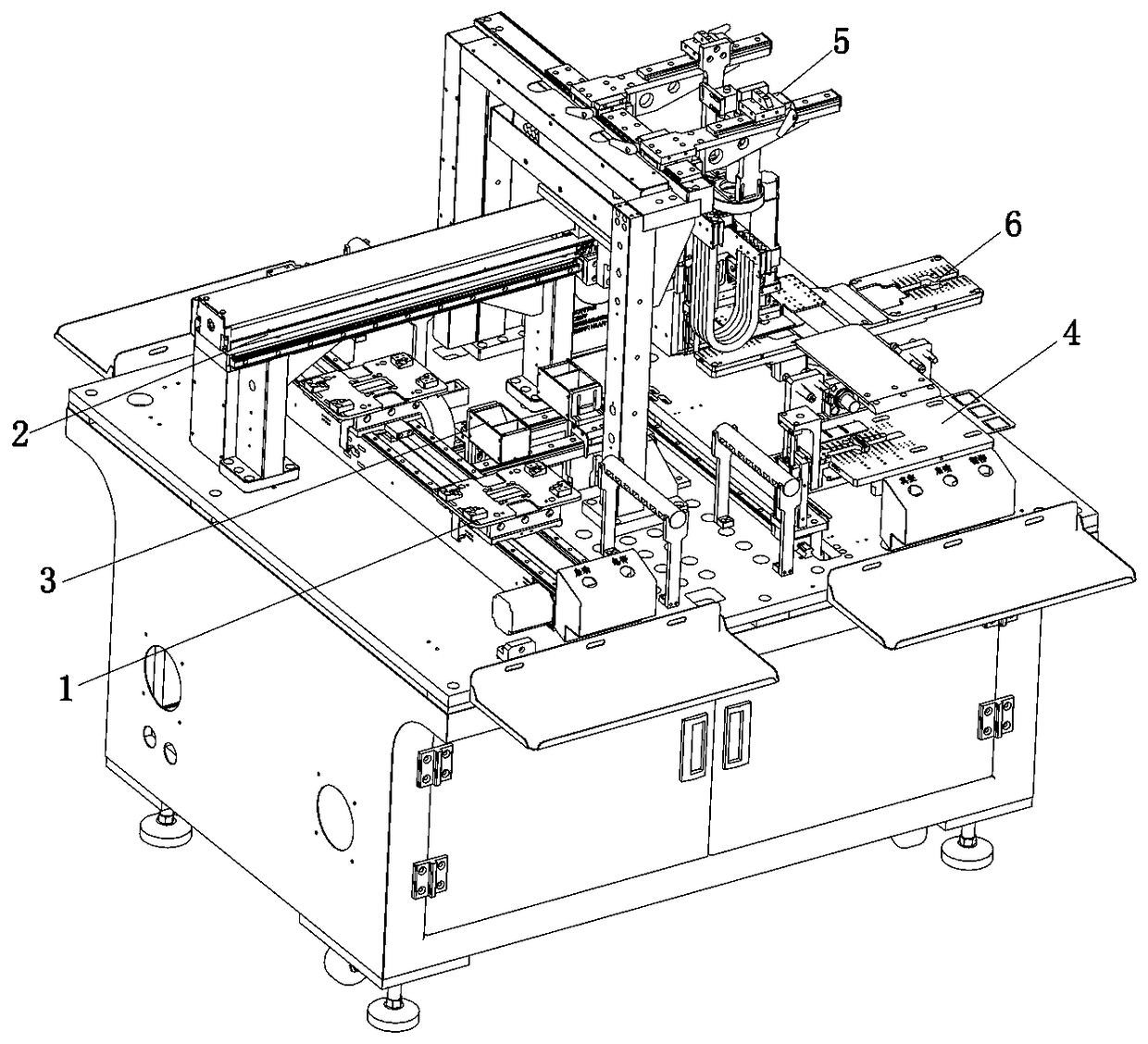
[0046]The above-mentioned pre-lamination part includes a glass sheet feeding mechanism 1, a placement robot 2, a TP film feeding platform 4 and a pre-lamination platform 6, wherein the above-mentioned glass sheet feeding mechanism 1 is arranged on the machine table, and the glass sheet to be bonded The above-mentioned pre-lamination platform 6 is arranged on one side of the glass sheet feeding mechanism 1 along the direction perpendicular to the glass sheet...


PUM


Abstract

The invention discloses a double-feeding vacuum fitting production line and a fitting process thereof. The double-feeding vacuum fitting production line comprises a pre-fitting portion and a vacuum fitting portion which are in parallel arrangement, a glass sheet and a TP film are mutually fitted to an integral filmed glass sheet on the pre-fitting portion, and the filmed glass sheet is vacuum fitted on the vacuum fitting portion; the pre-fitting portion comprises a glass sheet feeding mechanism, a fitting manipulator, a TP film feeding platform and a pre-fitting platform; the vacuum fitting portion is provided with at least two vacuum fitting workstations parallelly and comprises a sliding feeding platform, a feeding manipulator, a vacuum fitting mechanism and a discharging manipulator. Multiple vacuum fitting workstations are adopted, so that fitting efficiency is improved effectively, and individual clamping and fixing of a film and the glass sheet are not needed; positioning correction is not needed during vacuum fitting, so that requirements on accuracy during vacuum fitting are lowered and production cost are lowered; vacuum fitting time period is utilized to complete pre-fitting and material conveying, so that time utilization rate is increased, and improving of whole line production capacity is facilitated.

Description

technical field [0001] The invention relates to the field of automated manufacturing, in particular to a double-loading vacuum bonding production line and a bonding process thereof. Background technique [0002] With the continuous improvement of the consumption market of various smart terminal equipment and the shortening of the replacement cycle of smart terminal equipment year by year, the market demand for "screen" as an important accessory in smart terminal equipment is increasing year by year; at present, major domestic screen manufacturers carry out production lines Upgrading is the only way to improve market competitiveness; the main way to upgrade the production line is to replace the traditional assembly line operation with the automatic design of the whole line, to realize the automation and intelligence of the whole line, so as to optimize the production capacity, quality and manufacturing cost of the whole line . The screen manufacturing process involves a film...

Claims


Application Information

Patent Timeline
IPC IPC(8): B32B37/10B32B38/18
CPCB32B37/1018B32B38/1841
Inventor 许立峰邬兴国罗会冬樊克鹏陈代鹏
Owner SHENZHEN NUOFENG OPTOELECTRONICS EQUIP
Why Eureka
Eureka Blog
Learn More