Hydraulic design method of no-jam cyclone pump

A technology of hydraulic design and swirl pump, which is applied to components, pumps, and pump components of elastic fluid pumping devices, can solve problems such as energy waste and large hydraulic loss, and achieve reduced energy loss, improved efficiency, The effect of good economic benefits

Inactive Publication Date: 2014-08-20
JIANGSU UNIV
View PDF5 Cites 12 Cited by
  • Summary
  • Abstract
  • Description
  • Claims
  • Application Information

AI Technical Summary

Problems solved by technology

The medium near the top of the impeller outlet forms a through flow due to the large centrifugal force, and the medium in the middle of the impeller forms a circulating flow. It is precisely be...

Method used


Image

  • Hydraulic design method of no-jam cyclone pump
  • Hydraulic design method of no-jam cyclone pump
  • Hydraulic design method of no-jam cyclone pump

Examples


Embodiment Construction

[0039] The present invention will be further described below in conjunction with the accompanying drawings and specific embodiments, but the protection scope of the present invention is not limited thereto.

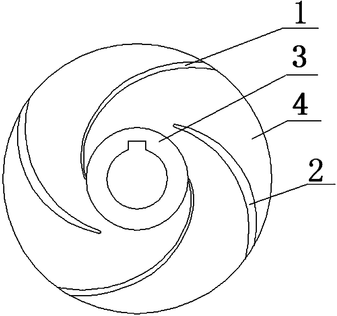
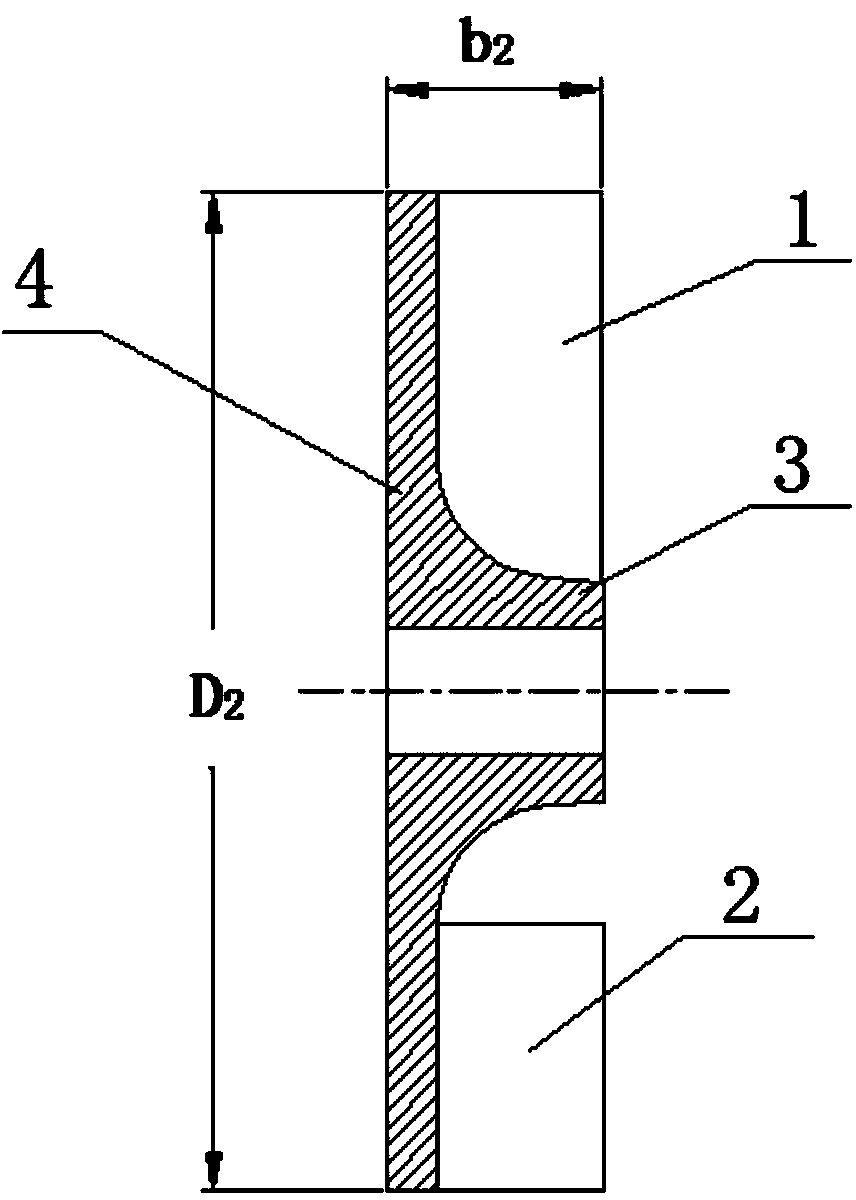
[0040] The hydraulic design method of the non-clogging swirl pump of the present invention, the impeller of the swirl pump is as figure 1 , figure 2 As shown, a semi-open impeller is selected, including a blade, a hub 3, and an impeller rear cover 4. The blade is arranged on one side of the impeller rear cover 4, and the hub 3 is located at the center of the impeller rear cover 4. The blades adopt several long blades and short blades with different lengths to improve the internal flow of the pump and improve the hydraulic performance and reliability of the swirl pump. Specifically, the length L of the long blade 1 with short blade length L 2 The ratio of The number of the long blades and the short blades is 2, and in order to keep the balance of the impeller, the tw...


PUM


Abstract

The invention provides a hydraulic design method of a no-jam cyclone pump. An impeller of the cyclone pump is a semi-opening-type impeller, blades of the impeller include long blades and short blades, the lengths of the blades are different, due to the facts that the diameter of an outlet of the impeller of the cyclone pump, the width of the outlet of the impeller, the specific value range of the long blades and the short blades of the impeller are optimized and hydraulic design is carried out by controlling F8 section area selection and increasing the volute throat area, conveyed solid media are easy to pass, the passing rate of the conveyed solid media are improved, the blocking phenomena are prevented, meanwhile, loss of circulation flow in the cyclone pump is reduced, and accordingly efficiency of the cyclone pump is improved, and economic efficiency is good in production practices.

Description

technical field [0001] The invention relates to a hydraulic design method of a swirl pump, in particular to a hydraulic design method of a non-blocking swirl pump. Background technique [0002] The swirl pump is a kind of centrifugal pump, which is named for the rotating vortex motion of the internal fluid. Swirl pumps are mostly used to pump complex media or fluids containing impurities, such as two-phase fluids containing garbage and short fiber substances. The internal flow of the swirl pump is very complicated. The blades retract into the blade chamber of the pump body and rotate. When the impeller rotates, the energy of the medium is increased by the centrifugal force, and the medium entering between the blades is pushed by the blades to move with the impeller. The medium near the top of the impeller outlet forms a through flow due to the large centrifugal force, and the medium in the middle of the impeller forms a circulating flow. It is precisely because of the exist...

Claims


Application Information

Patent Timeline
IPC IPC(8): F04D29/22F04D29/42
Inventor 王秀礼付强朱荣生王洪亮
Owner JIANGSU UNIV
Why Eureka
Try Eureka