
Drive device for the road wheels of a vehicle

A driving mechanism and wheel technology, applied in the direction of transmission, mechanical equipment, transmission parts, etc., can solve the problem of large agitation loss and achieve good lubrication effect

Inactive Publication Date: 2014-08-20
ZF FRIEDRICHSHAFEN AG
View PDF5 Cites 0 Cited by
  • Summary
  • Abstract
  • Description
  • Claims
  • Application Information

AI Technical Summary

Problems solved by technology

Especially at high rpm this leads to large churning losses

Method used


Image

  • Drive device for the road wheels of a vehicle

Examples


Embodiment Construction

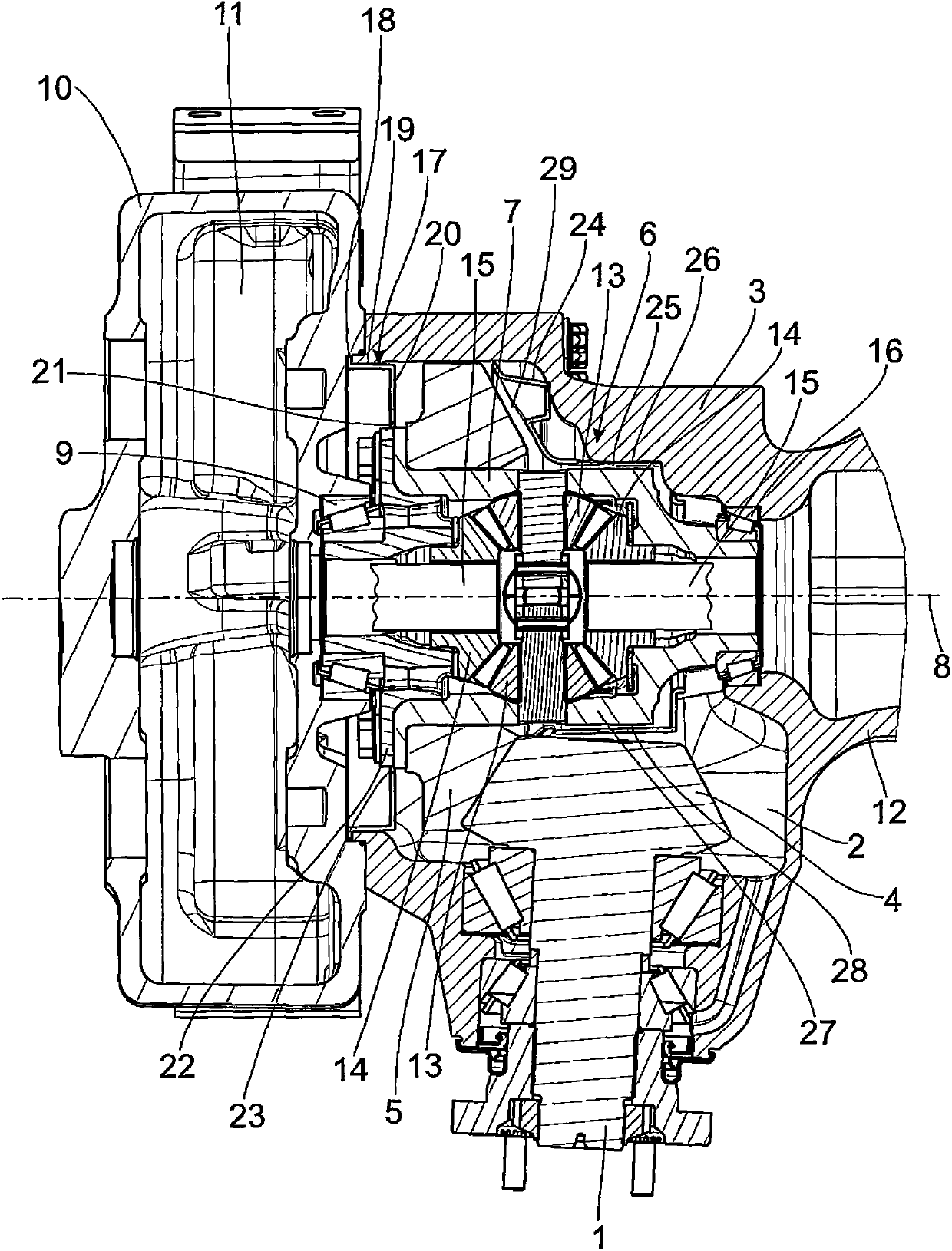
[0052] A drive shaft 1 , which is rotatable by an engine of the vehicle, is inserted approximately horizontally into a housing interior 2 of a housing 3 .

[0053] At its end protruding into the housing 3 , the drive shaft 1 has a drive gear 4 designed as a bevel gear, which meshes with a ring gear 5 of the differential unit 6 , which is also designed as a bevel gear.

[0054] The ring gear 5 is fixedly connected to the differential housing 7 and is rotatably mounted by means of the differential housing on two differential bearings 9 , 16 about an axis of rotation 8 extending at right angles to the axis of rotation of the drive shaft 1 superior.

[0055] The first differential bearing 9 is arranged on a carrier housing 10 which is connected to the housing 3 by means of a screw connection. Here too, the housing interior 2 is connected to the carrier housing interior 11 .

[0056] The housing 3 forms an axial end region of a tubular axle 12 axially relative to the axis of rota...


PUM


Abstract

A drive device for the road wheels of a vehicle, with a stationary housing partially filled with a lubricating liquid, and a rotatably drivable driveshaft inserted into the housing interior and with a differential unit having a crown wheel with a differential housing. The crown wheel is rotatably drivable by the driving gear wheel, by means of which crown wheel a plurality of differential gear wheels of the differential unit are rotatably drivable, driven gear wheels being rotatably drivable in turn by these differential gear wheels. The driven gear wheels being drivingly connected in each instance to driven shafts for driving the road wheels of the vehicle. The differential unit is enclosed in the housing interior by a shielding housing, wherein the stationary housing interior is connected to the shielding housing interior via one or more apertures.

Description

technical field [0001] The invention relates to a drive mechanism for a vehicle wheel, the drive mechanism having a fixed housing, the housing interior of which is partly filled with lubricating fluid, and into which a rotatable drive shaft is inserted, The drive shaft has a drive gear at its end protruding into the inner cavity of the housing, and the drive mechanism has a differential unit with a differential housing, rotatably supported in the housing, driven by a The gear drives a rotating ring gear, which drives a plurality of differential gears of the differential unit and which in turn drives driven gears, each of which is connected to a The driven shaft drive connection that drives the wheels of the vehicle. Background technique [0002] It is known in drives of this type that the differential unit is immersed in a lubricating fluid in the interior of the housing. Especially at high rotational speeds, this leads to large churning losses. Contents of the invention...

Claims


Application Information

Patent Timeline
Patent Type & Authority Applications(China)
IPC IPC(8): F16H48/40F16H57/04
CPCF16H48/06F16H48/08F16H57/0423F16H57/0409F16H57/0483F16H57/037F16H57/0424F16H57/0452F16H57/0493
Inventor H·西格尔P·伦茨
Owner ZF FRIEDRICHSHAFEN AG
Learn More