
Temperature-compensated optical current measurement module and temperature-compensated optical current transformer

A current transformer and current measurement technology, applied in the measurement of electrical variables, measurement of current/voltage, measurement devices, etc., can solve the problem that the optical current sensor cannot accurately measure the current, and achieve a large dynamic range of measurement, wide temperature range, measurement high precision effect

Inactive Publication Date: 2014-08-20
STATE GRID CORP OF CHINA +1
View PDF6 Cites 8 Cited by
  • Summary
  • Abstract
  • Description
  • Claims
  • Application Information

AI Technical Summary

Problems solved by technology

[0006] The purpose of the present invention is to provide a temperature-compensated optical current measurement module to solve the problem that the existing optical current sensor cannot accurately measure the current due to the influence of temperature, and to provide an optical current transformer using the optical current measurement module

Method used


Image

  • Temperature-compensated optical current measurement module and temperature-compensated optical current transformer
  • Temperature-compensated optical current measurement module and temperature-compensated optical current transformer
  • Temperature-compensated optical current measurement module and temperature-compensated optical current transformer

Examples


Embodiment Construction

[0018] The present invention will be further introduced below in conjunction with the accompanying drawings and specific embodiments.

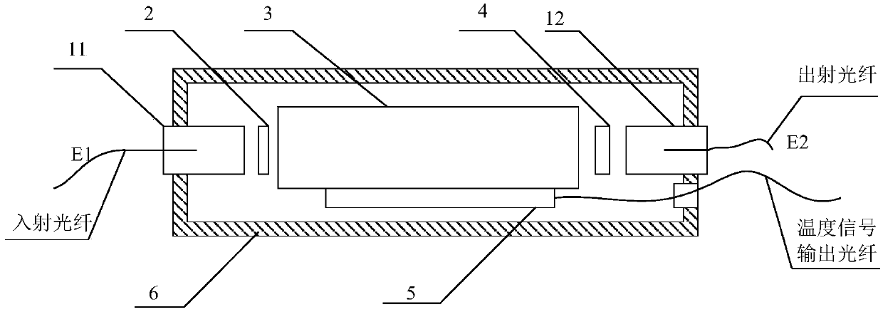
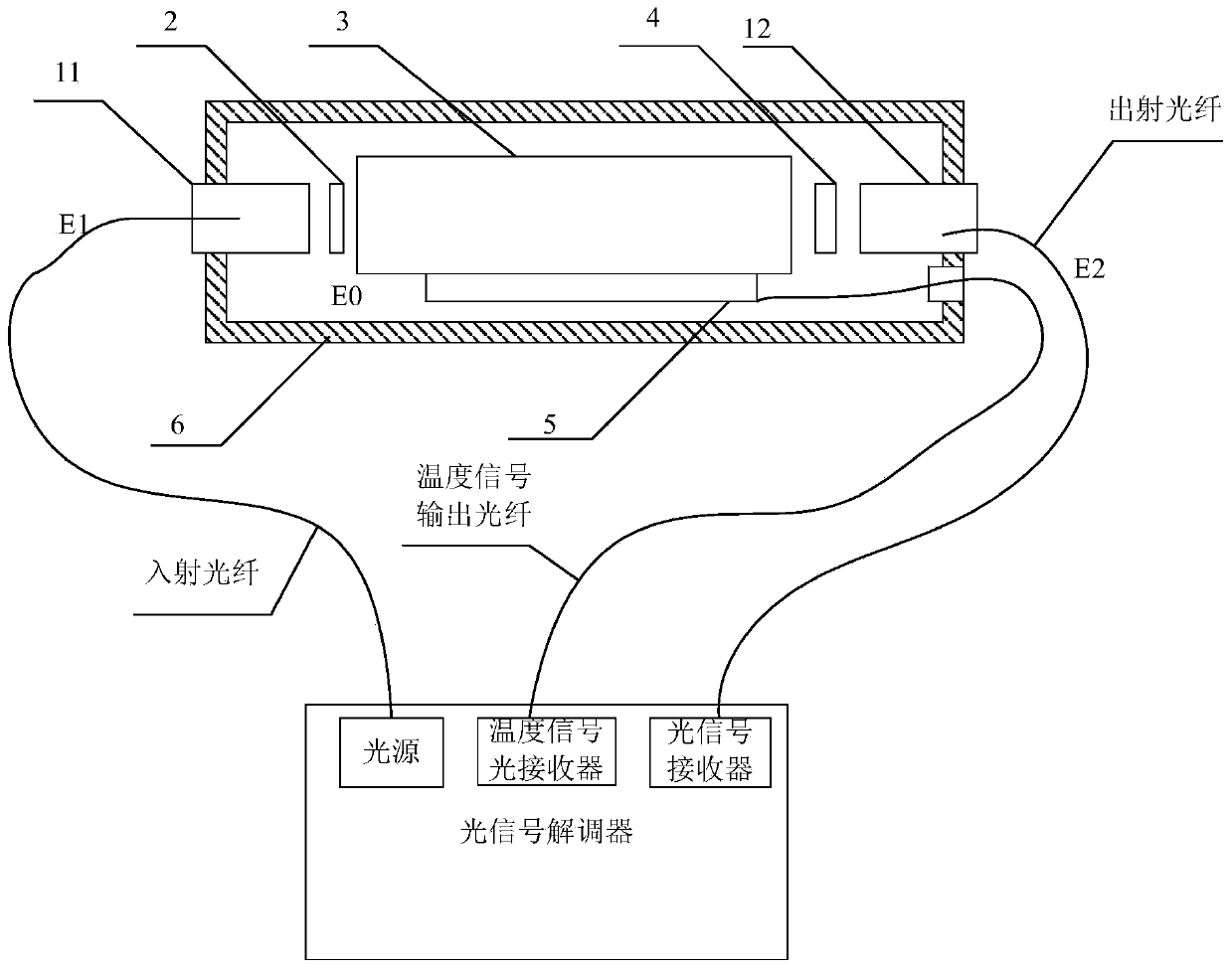
[0019] like figure 1 Shown is the structural principle diagram of the embodiment of the optical current measurement module with temperature compensation of the present invention. It can be seen from the figure that the measurement module includes an incident optical fiber for connecting with a light source and an outgoing optical fiber for connecting with an optical signal demodulator. A first self-focusing lens 11, a polarizer 2, a magneto-optical glass 3, an analyzer 4, and a second self-focusing lens 12 are sequentially arranged between the optical fiber and the outgoing fiber; Temperature sensor 5 for temperature.

[0020] The temperature sensor of this embodiment is an optical fiber temperature sensor, and the output signal of the optical fiber temperature sensor is connected with the temperature signal optical receiver of the optical si...


PUM


Abstract

The invention discloses a temperature-compensated optical current measurement module and a temperature-compensated optical current transformer. The optical current measurement module comprises an incident optical fiber used for being connected with a light source, and an emergent optical fiber used for being connected with an optical signal demodulator. A first self-focusing lens, a polarizer, a magneto-optic glass, an analyzer and a second self-focusing lens are sequentially arranged between the incident optical fiber and the emergent optical fiber. The surface of the magneto-optic glass is provided with a temperature sensor used for measuring the internal temperature of the magneto-optic glass. According to the invention, the temperature sensor is arranged on the surface of a measurement optical element to measure the internal temperature of the magneto-optic glass and sense the temperature change of the magneto-optic glass, measured current sensed by the magneto-optic glass is demodulated from an emergent optical signal E2, and then the coefficient of the Faraday magnetic declination of the magneto-optic glass is corrected through temperature compensation, thereby realizing accurate current compensation measurement. The optical current measurement module has high structural stability and high measurement precision, and has the characteristics of large dynamic range of measurement, no magnetic saturation, wide measurement frequency band and wide temperature range.

Description

technical field [0001] The invention relates to a temperature-compensated optical current measurement module and an optical current transformer. Background technique [0002] Due to the problems of ferromagnetic material saturation, DC component measurement and high-voltage insulation in traditional electromagnetic current transformers, with the development of my country's smart grid, it is necessary to solve these key technologies that affect the development of ultra-high voltage and ultra-high voltage. For this reason, In recent years, various forms of new electronic current transformers have been developed. Among them, optical current transformers based on the Faraday magneto-optic effect have excellent insulation performance, no transient magnetic saturation, large dynamic measurement range, wide frequency response, and anti-electromagnetic interference. With the advantages of strong capability, small size, light weight, and easy interface with digital equipment, it is the...

Claims


Application Information

Patent Timeline
IPC IPC(8): G01R15/24G01R19/00
Inventor 田志国池立江袁亮郑健刘伟魏少鹏史文强步梦琼郭亚强孙如京张贺薛晓敏
Owner STATE GRID CORP OF CHINA
Learn More