Synthetic aperture radar SAR imaging method and device
A technology of synthetic aperture radar and imaging method, which is applied in the directions of measuring devices, radio wave reflection/re-radiation, and utilization of re-radiation, etc., and can solve problems such as SAR image defocus, distortion, and SAR image blur
- Summary
- Abstract
- Description
- Claims
- Application Information
AI Technical Summary
Problems solved by technology
Method used
Image

Examples
Embodiment 1
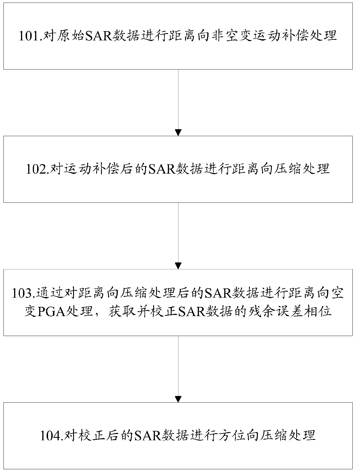
[0049] An embodiment of the present invention provides a SAR imaging method, such as figure 1 As shown, the method mainly includes the following steps:
[0050] Step 101, performing range-wise non-spatial motion compensation processing on the original SAR data;
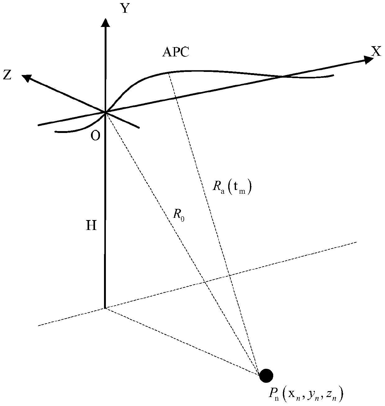
[0051] In this step, first, according to the geometric relationship between the actual flight path and the ideal flight path and the original SAR data in the navigation system, the motion error offset of the actual flight path relative to the ideal flight path is obtained, and according to the motion error of the original SAR data The offset is used to obtain the error phase of the original SAR data; and with the center of the observation scene as the reference point, the original SAR data is subjected to non-spatial motion compensation processing in the range direction according to the error phase of the original SAR data.
[0052] specifically, figure 2 Shows the geometric relationship between the actual flight p...
Embodiment 2
[0101] Compared with Embodiment 1, the embodiment of the present invention also provides a SAR imaging device, such as Figure 5 As shown, the device includes: a compensation module 51, a compression module 52, and a focus processing module 53; wherein,
[0102] The compensation module 51 is used to perform range-to-non-spatial motion compensation processing on the original SAR data; and correct the residual error phase of the SAR data according to the residual error phase of the SAR data sent by the focus processing module 53;
[0103] The compression module 52 is configured to perform range compression processing on the SAR data after motion compensation by the compensation module 51 ; and perform azimuth compression processing on the SAR data corrected by the compensation module 51 .
[0104] The focusing processing module 53 is used to obtain the residual error phase of the SAR data by performing range-space-varying PGA processing on the SAR data after the range compressio...
Embodiment 3
[0149] In order to verify the accuracy and reliability of the above embodiment, this embodiment takes a mountainous area with a resolution of 0.15 meters as an example, and uses the radar imaging method in the prior art solution and the radar imaging method provided by each embodiment of the present invention to analyze the SAR images for comparison. Figure 6 It shows a SAR image with defocus after motion compensation in the prior art; Figure 7 Shows the SAR image processed by the standard PGA in the prior art; Figure 8 The SAR images provided by the embodiments of the present invention are shown; it can be seen from these images that compared with the prior art, the SAR imaging method provided by the embodiments of the present invention can achieve precise focusing of the SAR image, thereby obtaining a good SAR images.
[0150] At the same time, this embodiment takes two observation scenes A and B in a mountainous area with a resolution of 0.15 meters, wherein, Figure ...
PUM
 Abstract
Description
Claims
Application Information
 - R&D Engineer
- R&D Manager
- IP Professional
- Industry Leading Data Capabilities
- Powerful AI technology
- Patent DNA Extraction
Browse by: Latest US Patents, China's latest patents, Technical Efficacy Thesaurus, Application Domain, Technology Topic.
© 2024 PatSnap. All rights reserved.Legal|Privacy policy|Modern Slavery Act Transparency Statement|Sitemap