
Configuration method and system for reactive power compensation of wind power plant

A configuration method and technology for wind farms, applied in reactive power adjustment/elimination/compensation, flexible AC transmission systems, wind power generation, etc., can solve problems such as large amount of calculation, not necessarily practical, cumbersome, etc. Space-saving, economical control solution

Active Publication Date: 2014-08-20
CHINA ENERGY ENG GRP GUANGDONG ELECTRIC POWER DESIGN INST CO LTD
View PDF6 Cites 22 Cited by
  • Summary
  • Abstract
  • Description
  • Claims
  • Application Information

AI Technical Summary

Problems solved by technology

The capacity of reactive power compensation will directly affect the economics of the project. Generally, the method of reactive power compensation capacity of wind farms is relatively cumbersome, the calculation amount is too large, and it is not necessarily practical. It is necessary to find a correct and simple method to determine Types and capacities of reactive power compensation in wind farms

Method used


Image

  • Configuration method and system for reactive power compensation of wind power plant
  • Configuration method and system for reactive power compensation of wind power plant
  • Configuration method and system for reactive power compensation of wind power plant

Examples


Embodiment Construction

[0019] The present invention will be described in further detail below in conjunction with the embodiments and accompanying drawings, but the embodiments of the present invention are not limited thereto.

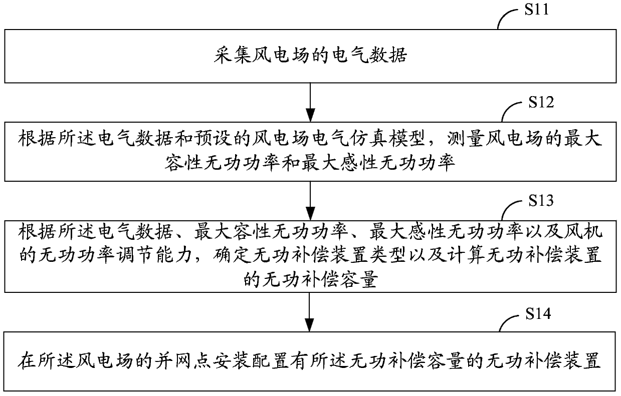
[0020] like figure 1 As shown, it is a schematic flow chart of the reactive power compensation configuration method of the wind farm in an embodiment of the present invention, including the following steps:

[0021] S11, collecting electrical data of the wind farm;

[0022] S12. Measure the maximum capacitive reactive power and the maximum inductive reactive power of the wind farm according to the electrical data and the preset electrical simulation model of the wind farm;

[0023] S13. Determine the type of the reactive power compensation device and calculate the reactive power compensation capacity of the reactive power compensation device according to the electrical data, the maximum capacitive reactive power, the maximum inductive reactive power, and the reactive power ...


PUM


Abstract

The invention discloses a configuration method for reactive power compensation of a wind power plant. The configuration method for reactive power compensation of the wind power plant comprises the following steps that electrical data of the wind power plant are acquired; the maximum capacitive reactive power and the maximum lagging reactive power of the wind power plant are measured according to the electrical data and a preset wind power plant electrical simulation model; the type of a reactive power compensation device is determined and the reactive power compensation capacity of the reactive power compensation device is calculated according to the electrical data, the maximum capacitive reactive power, the maximum lagging reactive power and the reactive power regulation capacity of a draught fan, wherein the reactive power compensation device comprises a parallel reactor, a parallel capacitor and / or an SVA device; the reactive power compensation device with the reactive power compensation capacity is installed and configured on a grid connection point of the wind power plant. The invention further provides a system corresponding to the configuration method. By the adoption of the system, the type and the capacity of reactive power compensation can be determined rapidly, easily and conveniently.

Description

technical field [0001] The invention relates to the technical field of wind farms, in particular to a configuration method for wind farm reactive power compensation and a configuration system for wind farm reactive power compensation. Background technique [0002] As the global energy crisis continues, new energy, especially wind power, is developing rapidly around the world. Compared with land wind power, offshore wind farms have the advantages of good wind resources, high annual power generation, and less land occupation. They have developed rapidly in recent years. [0003] In the research and design of offshore wind farms, reactive power compensation is a very important issue, which directly affects the power factor and voltage level of the wind farm being assessed, as well as the reactive power support capability of the wind farm. For the reactive power configuration of offshore wind farms, including the type selection, capacity selection, and location selection of reac...

Claims


Application Information

Patent Timeline
IPC IPC(8): H02J3/18
CPCY02E10/763Y02E40/12Y02E10/76Y02E40/10
Inventor 谭任深周伟李煜东汪少勇谭江平郑明徐龙博陈楠
Owner CHINA ENERGY ENG GRP GUANGDONG ELECTRIC POWER DESIGN INST CO LTD
Learn More