WLAN device dynamic channel allocation method based on alliance

A dynamic channel allocation and dynamic channel technology, applied in wireless communication, electrical components, etc., can solve problems such as dynamic grouping and channel selection, and achieve the effects of reducing management workload, accelerating convergence speed, and shortening convergence time

Active Publication Date: 2014-08-20
BEIJING JIAOTONG UNIV
View PDF2 Cites 13 Cited by
  • Summary
  • Abstract
  • Description
  • Claims
  • Application Information

AI Technical Summary

Problems solved by technology

[0008] The purpose of the present invention is to solve the problem of dynamic grouping and channel selection when deploying APs in a large scale by designing a method

Method used


Image

  • WLAN device dynamic channel allocation method based on alliance
  • WLAN device dynamic channel allocation method based on alliance

Examples


Embodiment Construction

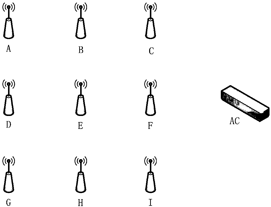
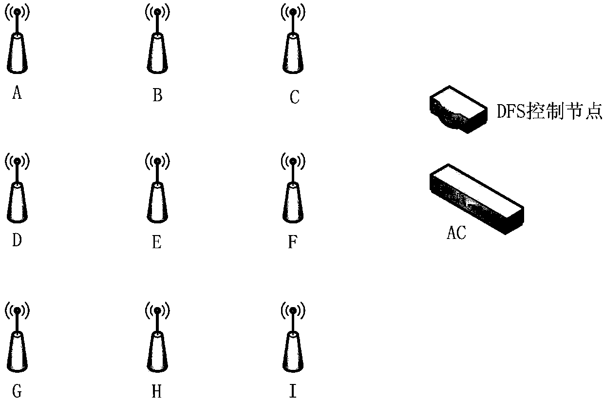
[0017] The present invention provides a technical solution for dynamically selecting AP groups and dynamically allocating channels within the group. Such as figure 2 As shown, in the AC-AP architecture, the DFS control node can be deployed on the AC, or deployed on the server, or can form a separate product. In a non-AC-AP architecture such as a pure FATAP network, the DFS control node can be deployed on a server or a separate product. The DFS control node periodically collects AP information, including RSSI, CRC error rate, retransmission times, bit error rate, etc., to form a network topology map; run an optimization strategy to segment the network topology map, and the divided topology subgraphs form DFS Grouping; select the root node in the DFS group, and select channels sequentially from the root node.

[0018] The present invention provides a method for automatically dividing a DFS group based on an alliance, and its specific technical scheme is as follows:

[0019] ...


PUM


Abstract

The invention discloses a WLAN device dynamic channel allocation method based on an alliance. The WLAN device dynamic channel allocation method includes the steps that a DFS control node collects and maintains information including current channels, ID of neighbor AP nodes and the like of AP nodes to generate a DFS network topological graph; the DFS network topological graph is divided into independent communicated sub-graphs, and DFS groups are formed by the final divided sub-graphs; as for the DFS groups without boundary division nodes, the nodes, with the highest total receiving signal intensity, in the DFS groups are selected as starting nodes of a dynamic channel selection algorithm; as for the DFS groups with multiple boundary division nodes, the division nodes with the highest total receiving signal intensity are selected as starting nodes of the dynamic channel selection algorithm; beginning with the starting nodes, neighbors with the highest total receiving signal intensity are preferentially selected to carry out channel selection. By means of the WLAN device dynamic channel allocation method, the convergence rate of whole network dynamic channel adjustment is increased through the grouping technology, and the channel selection convergence time is shortened.

Description

technical field [0001] The invention relates to the field of information technology, in particular to the field of a wireless local area network. Background technique [0002] Because it can provide high-speed wireless connection services, WLAN (Wireless Local Access Network, wireless local area network) is one of the relatively popular technologies in the IT (Information Technology, information technology) industry at present, and it is also a popular wireless access method. The WLAN generally adopts a centralized AC (Access Controller, wireless controller)-AP (Access Point, wireless access point) architecture. The AC provides centralized management of the WLAN network, and the AP establishes a link with the AC to join the WLAN network and provides wireless access services (such as figure 1 shown). [0003] In wireless applications, because wireless signal propagation is affected by the surrounding environment, multipath and other issues lead to complex attenuation of wir...

Claims


Application Information

Patent Timeline
Patent Type & Authority Applications(China)
IPC IPC(8): H04W72/04
Inventor 张志飞
Owner BEIJING JIAOTONG UNIV
Why Eureka
Try Eureka