

Vehicle seat
A vehicle and seat technology, applied in vehicle seats, vehicle parts, vehicle safety arrangements, etc., can solve the problem of not considering time, etc., and achieve the effect of a simple structure
- Summary
- Abstract
- Description
- Claims
- Application Information
AI Technical Summary
Problems solved by technology
Method used
Image

Examples
Embodiment Construction
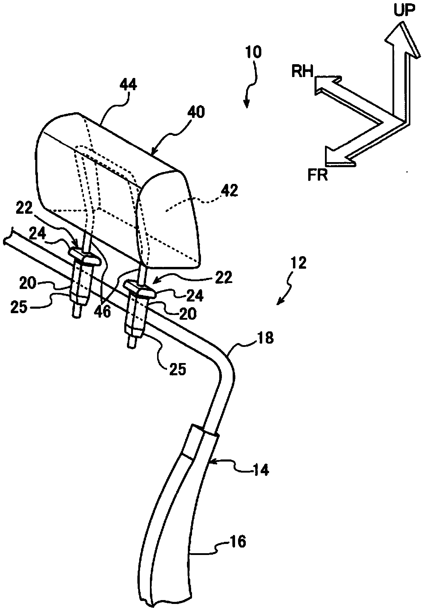
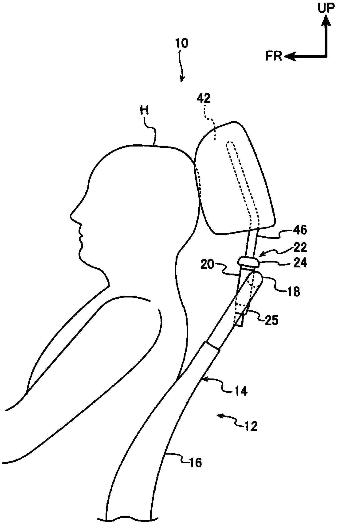
[0035] exist figure 1 In , the main part of the vehicle seat 10 according to the embodiment of the present invention is shown in a perspective view viewed from the left front of the vehicle. figure 2 In , a main part of the vehicle seat 10 is shown in a side view viewed from the left side of the vehicle. In addition, in the drawings, the front of the vehicle is indicated by an arrow FR, the right side of the vehicle (one side in the vehicle width direction) is indicated by an arrow RH, and the upward direction is indicated by an arrow UP.
[0036] As shown in the above figure, the vehicle seat 10 includes a seat back 12 . The seat back 12 is arranged in a state of being erected at a vehicle rear end portion of a seat cushion (not shown) constituting the vehicle seat 10 , and is configured to be able to hold the upper body of the occupant.
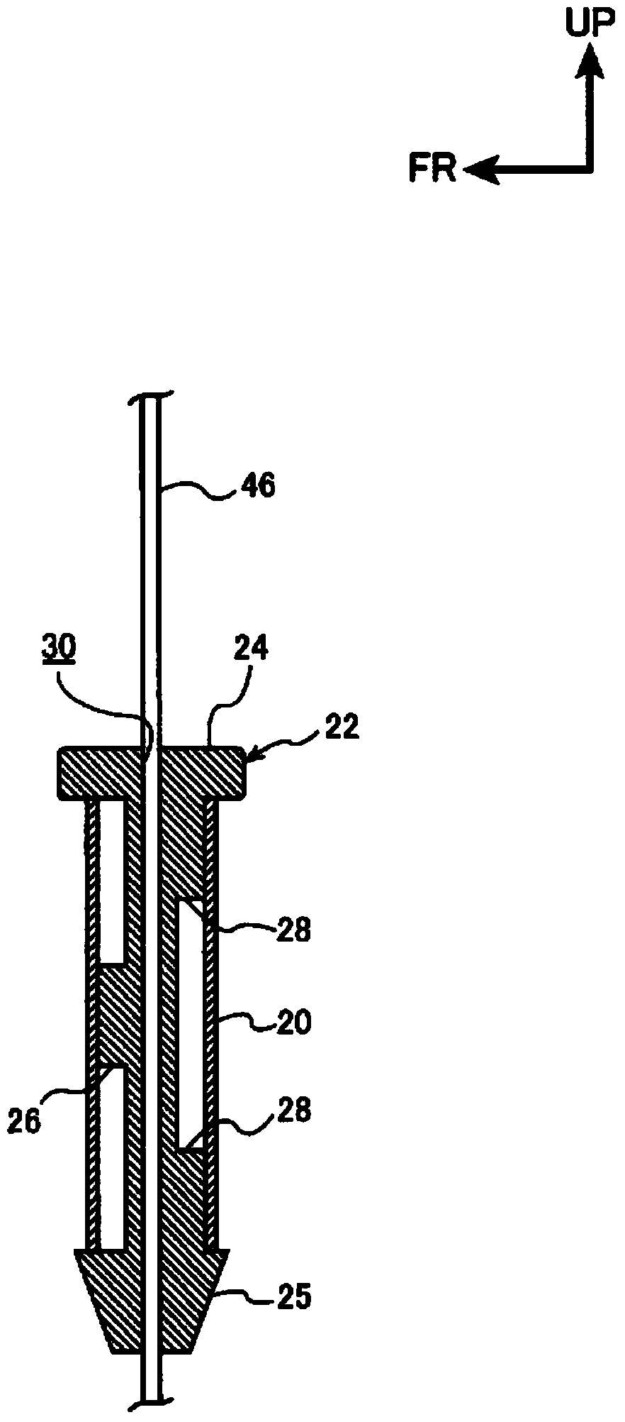
[0037] A seat back frame 14 is provided inside the seat back 12 , and the seat back frame 14 is connected to a cushion frame (not shown...
PUM
 Abstract
Description
Claims
Application Information