Wind turbine

A technology for wind power generation devices and generators, which is applied to wind turbine components, wind energy power generation, wind turbines, etc., can solve problems such as complexity and increase structural space, and achieve the effect of high efficiency and simple rotary structure.

Active Publication Date: 2014-08-20
VOITH PATENT GMBH
View PDF6 Cites 0 Cited by
  • Summary
  • Abstract
  • Description
  • Claims
  • Application Information

AI Technical Summary

Problems solved by technology

This is relatively complex and increases the necessary installation space in the region of the nacelle of the wind power plant carrying the rotor

Method used


Image

  • Wind turbine
  • Wind turbine
  • Wind turbine

Examples


Embodiment Construction

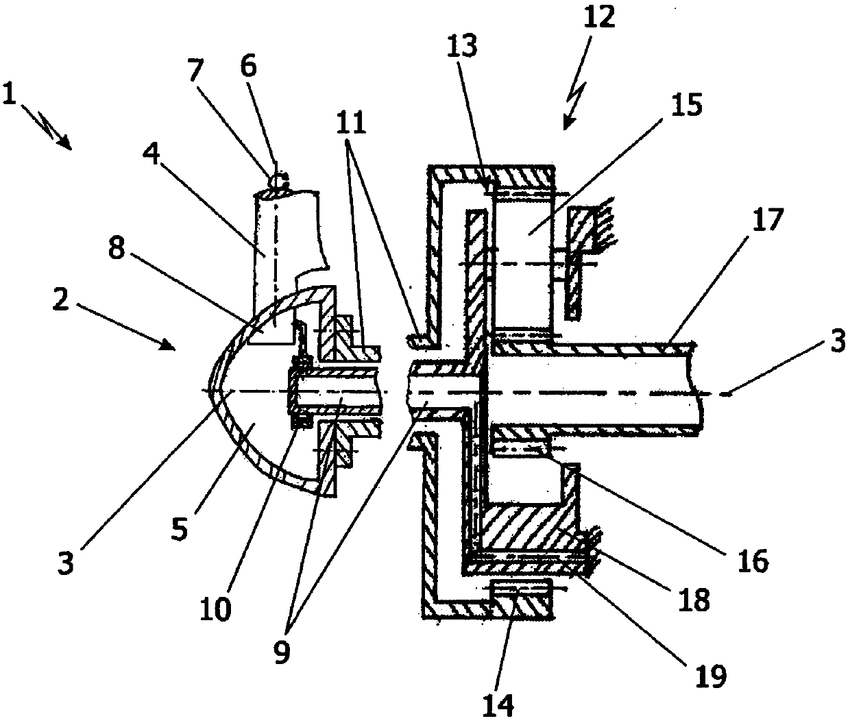
[0016] exist figure 1 Parts of the wind power plant 1 that are relevant to the invention can be seen in the view of . This part essentially consists of the rotor 2 rotating about the rotor axis 3 . The rotor 2 is formed from a plurality of rotor blades 4 , only one of which is schematically shown in this section. The rotor blades 4 converge into a central rotor hub 5 . The rotor blade 4 is adjustable about its own longitudinal axis 6 , which is generally, but not necessarily, perpendicular to the axis of rotation 3 , as is shown schematically by the arrow designated 7 . The adjustment of the rotor blades 4 is known from the prior art. This adjustment is typically effected from the inside of the rotor hub 5 via an adjustment device 8 , which is again only shown as a box. However, the configuration of the adjusting device 8 is known from the prior art.

[0017] In order to operate the adjusting device 8 , adjusting energy must be delivered into the region of the rotor hub 5...


PUM


Abstract

The invention relates to a wind turbine comprising - a rotor which rotates about a rotor axis, - rotor blades which converge in a central rotor hub and which are designed to be adjustable, - a transmission which is connected at least indirectly to the rotor on the drive side and at least indirectly to a generator on the output side, and - supply lines for adjustment energy, said supply lines being led through the transmission and into the rotor hub. The invention is characterized in that - the transmission comprises at least one planetary stage with a stationary planet carrier and - the supply lines for the adjustment energy run through the stationary planet carrier and through a supply channel arranged centrally about the rotor axis.

Description

technical field [0001] The invention relates to a wind power plant of the type approximately defined in the preamble of claim 1 . Background technique [0002] Wind power plants are already known from the prior art. Such wind power plants typically have a wind-driven rotor that rotates about a rotor axis. In order to ensure the adjustability of the wind turbine, the rotor blades converging into the central rotor hub are designed to be adjustable. The rotor blades are rotatable about a longitudinal axis, which is typically perpendicular to the rotor shaft, so that the profile of the individual rotor blades can be adapted to the required power ratio and / or the prevailing wind speed. For this purpose, an adjusting device with the rotation of the rotor is known in the region of the rotor hub, which must be supplied with adjusting energy in order to be able to adjust the rotor blades. The adjustment devices are mostly designed hydraulically or electrically. It is therefore ne...

Claims


Application Information

Patent Timeline
Patent Type & Authority Applications(China)
IPC IPC(8): F03D11/00F03D11/02F03D7/02
CPCF05B2260/79F05B2260/40311F05B2270/602Y02E10/721Y02E10/722F05B2270/604F03D11/005F05B2270/60F03D80/80Y02E10/72
Inventor 拉尔夫·布克哈特伯恩哈德·牧鹅曼努埃尔·瑞斯格
Owner VOITH PATENT GMBH
Why Eureka
Try Eureka