

Novel pneumatic manipulator
A technology of pneumatic manipulators and manipulators, which is applied in the direction of manipulators, program-controlled manipulators, chucks, etc., can solve the problems of high control precision, complex control structure, and low reliability, so as to improve production efficiency, improve work accuracy, and facilitate control. Effect
- Summary
- Abstract
- Description
- Claims
- Application Information
AI Technical Summary
Problems solved by technology
Method used
Image

Examples
Embodiment 1
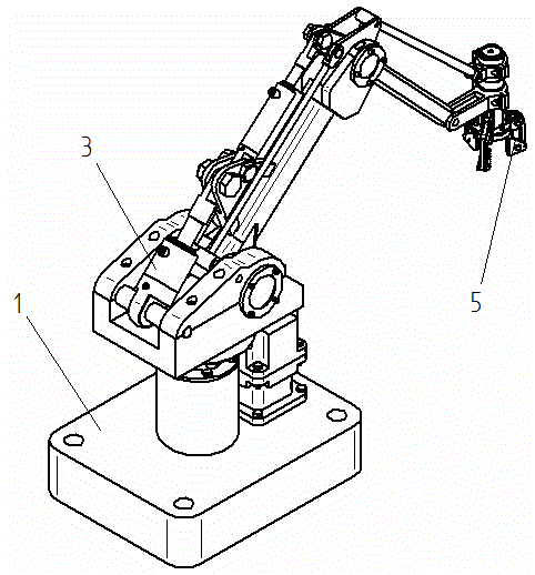
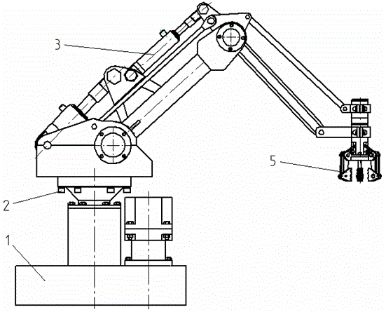
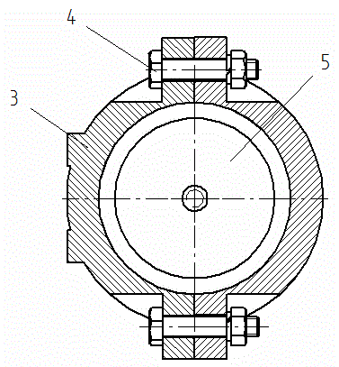
[0035] Embodiment 1: as Figure 1-8 As shown, a new type of pneumatic manipulator includes three major parts: base 1, manipulator arm 3, and manipulator gripper 5; the base 1 and manipulator arm 3 are connected together by hexagon socket head cap screws I2, and manipulator arm 3 and manipulator gripper 5 pass through The connecting bolt 4 is connected as a whole.
[0036] The base 1 includes a servo motor 6, a driving gear 7, a base body 8, a lock nut I 9, a large gear 10, a shaft sleeve 11, a thrust bearing 12, a positioning spacer 13, a rotating main shaft 14, an angular contact bearing 15, and a bearing end Cover I16; the servo motor 6 is installed on the base body 8 through threaded connection, the drive gear 7 is set on the drive shaft end of the servo motor 6, the thrust bearing 12 is installed in the cavity on the base body 8, and the positioning spacer 13 is installed on the thrust Above the bearing 12, the angular contact bearing 15 is installed above the positioning...
Embodiment 2
[0044] Embodiment 2: as Figure 1-8As shown, a new type of pneumatic manipulator includes three major parts: base 1, manipulator arm 3, and manipulator gripper 5; the base 1 and manipulator arm 3 are connected together by hexagon socket head cap screws I2, and manipulator arm 3 and manipulator gripper 5 pass through The connecting bolt 4 is connected as a whole.
[0045] The base 1 includes a servo motor 6, a driving gear 7, a base body 8, a lock nut I 9, a large gear 10, a shaft sleeve 11, a thrust bearing 12, a positioning spacer 13, a rotating main shaft 14, an angular contact bearing 15, and a bearing end Cover I16; the servo motor 6 is installed on the base body 8 through threaded connection, the drive gear 7 is set on the drive shaft end of the servo motor 6, the thrust bearing 12 is installed in the cavity on the base body 8, and the positioning spacer 13 is installed on the thrust Above the bearing 12, the angular contact bearing 15 is installed above the positioning ...
Embodiment 3
[0053] Embodiment 3: as Figure 1-8 As shown, a new type of pneumatic manipulator includes three major parts: base 1, manipulator arm 3, and manipulator gripper 5; the base 1 and manipulator arm 3 are connected together by hexagon socket head cap screws I2, and manipulator arm 3 and manipulator gripper 5 pass through The connecting bolt 4 is connected as a whole.
[0054] The base 1 includes a servo motor 6, a driving gear 7, a base body 8, a lock nut I 9, a large gear 10, a shaft sleeve 11, a thrust bearing 12, a positioning spacer 13, a rotating main shaft 14, an angular contact bearing 15, and a bearing end Cover I16; the servo motor 6 is installed on the base body 8 through threaded connection, the drive gear 7 is set on the drive shaft end of the servo motor 6, the thrust bearing 12 is installed in the cavity on the base body 8, and the positioning spacer 13 is installed on the thrust Above the bearing 12, the angular contact bearing 15 is installed above the positioning...
PUM
 Abstract
Description
Claims
Application Information