
Miniature helicopter undercarriage

A technology for helicopters and landing gear, which is applied in the field of aircraft, can solve the problems of time-consuming and laborious assembly of the fuselage, and poor impact resistance of the landing gear, and achieve the effects of saving time, reducing weight and prolonging the service life of the assembly process

Inactive Publication Date: 2014-08-27
杨雅茹
View PDF6 Cites 3 Cited by
  • Summary
  • Abstract
  • Description
  • Claims
  • Application Information

AI Technical Summary

Problems solved by technology

[0004] The purpose of the present invention is to propose a micro-helicopter landing gear to solve the problem of poor impact resistance of the landing gear and time-consuming and laborious assembly process with the fuselage in the prior art

Method used


Image

  • Miniature helicopter undercarriage
  • Miniature helicopter undercarriage
  • Miniature helicopter undercarriage

Examples


Embodiment 1

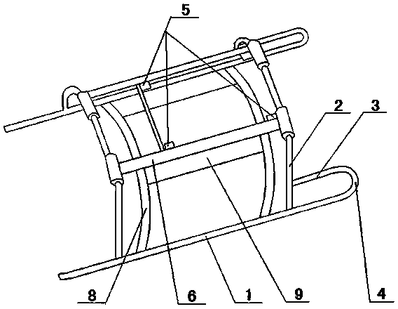
[0023] Such as Figure 1 to Figure 3 Shown, be a kind of micro-helicopter undercarriage that present embodiment proposes, comprise two braces 1 that are arranged in parallel, all be provided with on each brace 1 and brace 1 is the support bar 2 that is set angle inclination, as A preferred embodiment, the inclination angle is 15o. It also includes a cross bar 3 connected to the support bar 2 , and the cross bar 3 is connected to the support foot 1 through a transition bar 4 . In this embodiment, the cross bar 3 is connected with the transition bar 4 in an arc; the transition bar 4 is connected with the support foot 1 in an arc.

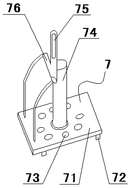
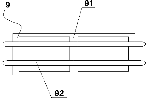
[0024] Mounting bases 6 for installing machine bases 7 are provided between the support rods 2 , and mounting holes 5 in a rectangular distribution are provided on the mounting bases 6 . Wherein, machine base 7 comprises chassis 71 and is located on the shaft seat 74 on chassis 71, and the bottom surface of chassis 71 is provided with the machine ba...

Embodiment 2

[0030] The difference between this embodiment and Embodiment 1 is that in this embodiment, the cross bar and the transition bar are connected at right angles, and the cross bar and the support feet are also connected at right angles.

[0031] In this embodiment, a partition for installing the control device is fixedly arranged on one side of the supporting foot, and a through hole for reducing weight is provided on the partition.

[0032] In this embodiment, the landing gear and the machine base are installed together, so that the assembly process is more time-saving and labor-saving, and at the same time, the whole body structure is more compact. At the same time, since there are through holes on the chassis of the machine base and the partition plate, the weight of the whole machine body is reduced, and the disassembly and assembly are more convenient.


PUM


Abstract

The invention relates to the technical field of air vehicles, and discloses a miniature helicopter undercarriage. The miniature helicopter undercarriage comprises two supporting feet arranged in parallel. Each supporting foot is provided with a supporting rod inclined at a set angle relative to the supporting foot. The miniature helicopter undercarriage further comprises transverse rods connected with the supporting rods, and the transverse rods are connected with the supporting feet through transition rods. An installation base for installing a helicopter base is arranged between the supporting rods. A supporting frame is arranged below the installation base and provided with a supporting structure. According to the miniature helicopter undercarriage, the transverse rods and the transition rods are arranged on the supporting feet, the impact resistant capacity of the supporting feet during landing is greatly improved, damage, caused by impacting, to a helicopter during landing is avoided, and the service life is effectively prolonged; the supporting structure is arranged, the impact resistance of the undercarriage is further improved, and the stability of a helicopter body in the flying process is improved; the undercarriage and the helicopter base are installed together, time and labor are saved in the assembling process, and meanwhile the whole helicopter body structure is compact.

Description

technical field [0001] The invention relates to the technical field of aircraft, in particular to a miniature helicopter landing gear. Background technique [0002] The landing gear is an accessory device set at the lower part of the aircraft to support the aircraft and move on the ground (or water surface) when the aircraft takes off and lands on the ground or slides on the water surface. It is an indispensable and important part of the aircraft. A downed aircraft cannot move on the ground. The landing gear is the only part used to support the entire aircraft, and the landing gear must withstand a certain impact when the body falls to the ground. The landing gear structure in the prior art is easily subjected to the recoil force of the bottom surface during the landing process. After a period of use, the contact part between the straight pipe and the connecting rod is easily broken, and the fuselage is damaged. [0003] The landing gear of the micro-helicopter in the prio...

Claims


Application Information

Patent Timeline
Patent Type & Authority Applications(China)
IPC IPC(8): B64C25/02B64C25/04
Inventor 韩世宇
Owner 杨雅茹
Learn More