Buffer piston energy accumulator

A buffer piston and accumulator technology, applied in mechanical equipment and other directions, can solve the problems of high pressure, high heat, and shorten the service life of the accumulator, and achieve the effects of prolonging the service life, low manufacturing cost, and adjustable buffer effect.

Inactive Publication Date: 2014-08-27
SANY HEAVY EQUIP
View PDF6 Cites 4 Cited by
  • Summary
  • Abstract
  • Description
  • Claims
  • Application Information

AI Technical Summary

Problems solved by technology

[0003] In view of this, the present invention proposes a cushioning piston accumulator to solve the problem that the piston of the prior art piston-type accumulator hits the bottom and generates noise. After a long time, local high heat and high pressure will be generated, reducing the storage capacity. Energy life issues

Method used


Image

  • Buffer piston energy accumulator
  • Buffer piston energy accumulator
  • Buffer piston energy accumulator

Examples


Embodiment

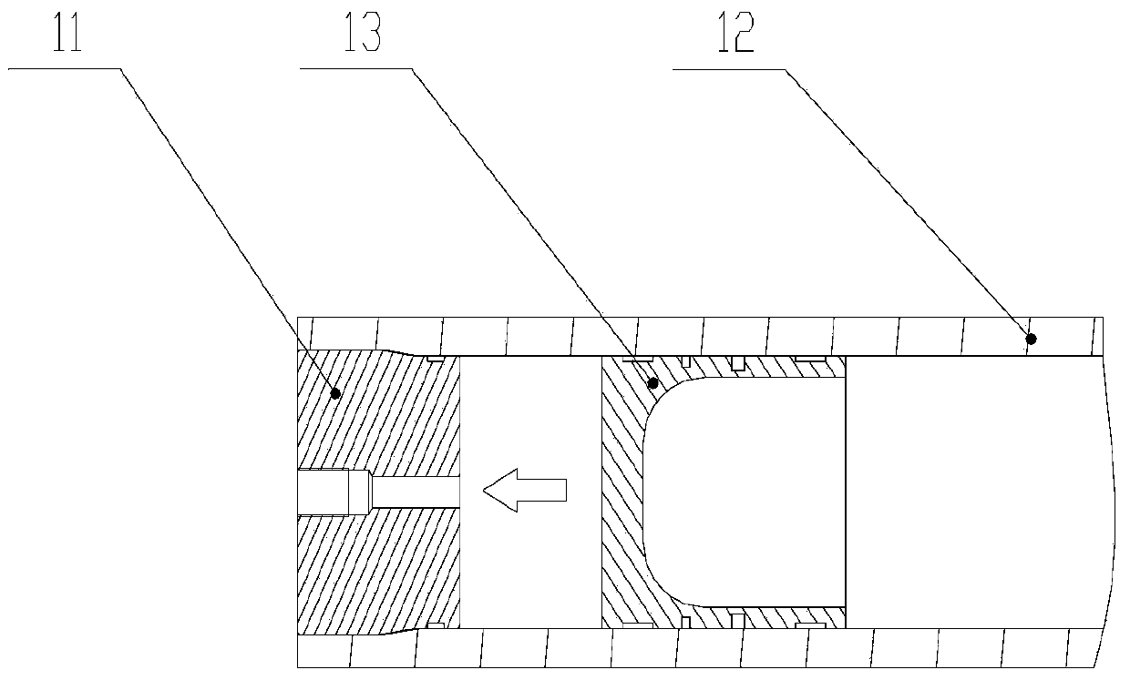
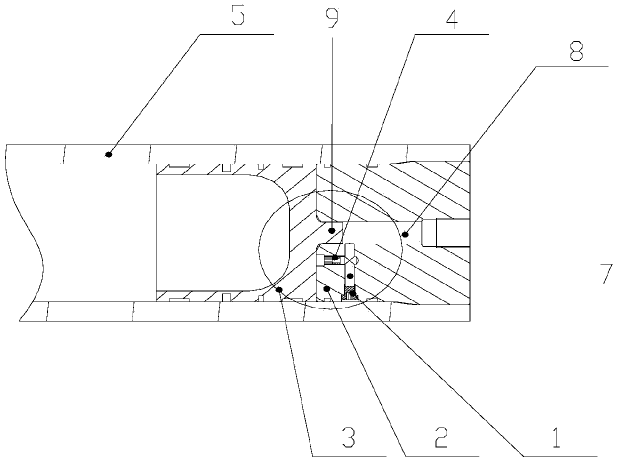
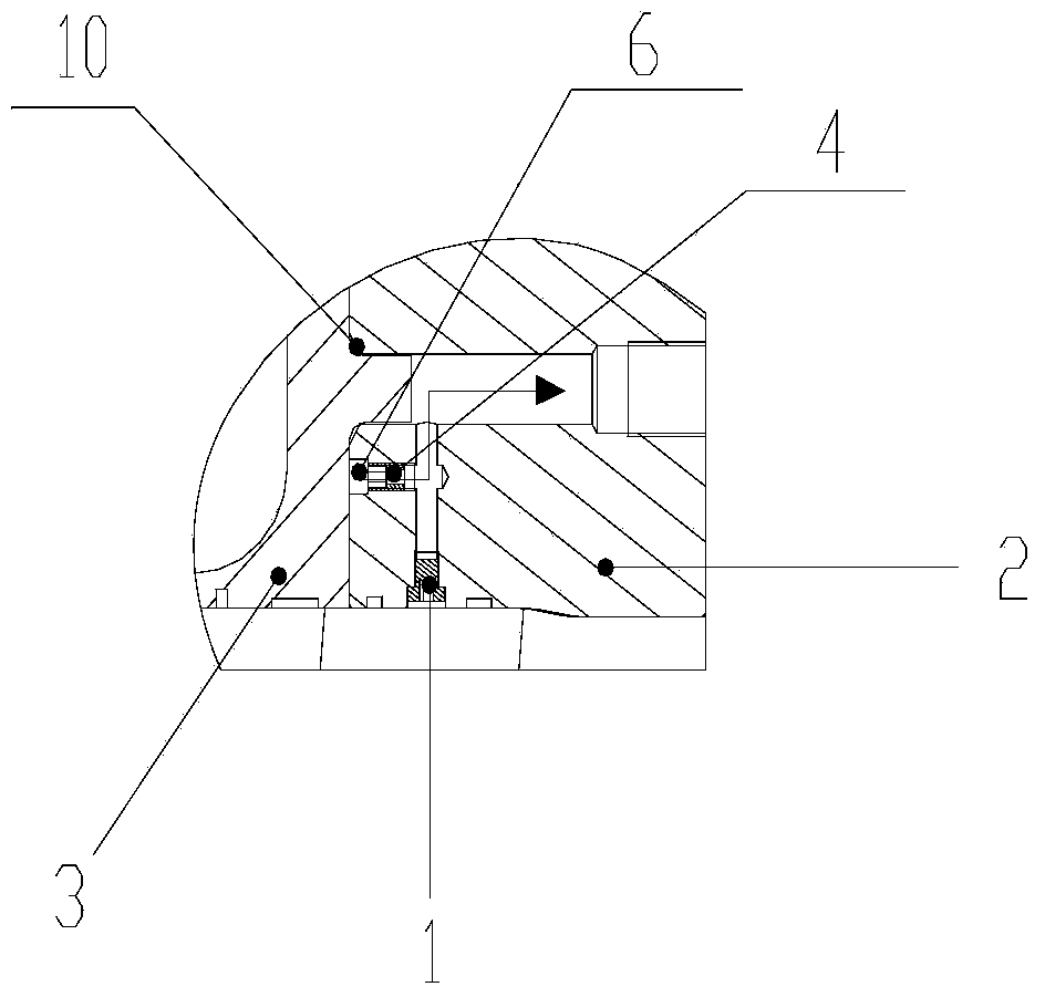
[0020] See figure 2 and image 3 As shown, a buffer piston accumulator of the present invention, the buffer piston accumulator is composed of a cylinder 5, a cylinder end cover 2 and a piston 3, the cylinder end cover 2 is arranged at one end of the cylinder 5, and the piston 3 is arranged In the cylinder body 5 and on one side of the cylinder end cover 2, an oil discharge port 8 is provided at the center of the cylinder end cover 2, and the oil discharge port 8 runs through the cylinder end cover 2. It is characterized in that the piston 3 is relatively One side of the cylinder end cover 2 is provided with a protrusion 9, the cylinder end cover 2 is provided with a buffer hole 6 relative to the surface of the piston 3, a throttling plug 4 is installed in the buffer hole 6, and the side of the cylinder end cover 2 is opened There is a process hole 7, and a process plug 1 is installed in the process hole 7. When the piston 3 moves to the cylinder end cover 2, the protrusion 9...


PUM


Abstract

The invention discloses a buffer piston energy accumulator. According to the buffer piston energy accumulator, an end cover of a cylinder body is arranged at one end of the cylinder body, a piston is arranged in the cylinder body and located at one side of the end cover of the cylinder body, an oil discharge opening is formed in the circle center of the end cover of the cylinder body and penetrates through the end cover of the cylinder body, one side, opposite to the end cover of the cylinder body, of the piston is provided with a boss, the surface, opposite to the piston, of the end cover of the cylinder body is provided with a buffer hole, a throttle plug is arranged in the buffer hole, the side face of the end cover of the cylinder body is provided with a process hole, and a process plug is arranged in the process hole. When the piston moves towards the end cover of the cylinder body, the boss plugs up the oil discharge opening to enable oil to flow to the oil discharge opening through the throttle plug, and the section area of the throttle plug is far smaller than that of the oil discharge opening, so that the movement speed of the piston is reduced, and the buffer effect is achieved. The buffer piston energy accumulator is simple in structure, adjustable in buffer effect and low in manufacturing cost, eliminates abnormal sounds of the hydraulic system generated when the piston hits against the end cover of the cylinder body, eliminates hydraulic impact generated when the piston hits against the end cover of the cylinder body and prolongs the service life of the energy accumulator and sealing pieces.

Description

technical field [0001] The invention relates to an accumulator, in particular to a buffer piston accumulator. Background technique [0002] Piston accumulator is one of the commonly used accumulators in hydraulic system. Due to its simple structure and easy manufacture, it has been widely used in hydraulic system. like figure 1 as shown, figure 1 It is a structural diagram of a piston accumulator in the prior art, and the piston accumulator is composed of a cylinder body 12, a piston 13, a seal, and front and rear end covers 11. At present, most of the commonly used piston accumulators on the market do not have a buffer device. In actual work, the phenomenon of piston hitting the bottom often occurs; the bottoming phenomenon will generate excessive hydraulic shock to the seal inside the piston while generating noise. , resulting in local high heat and high pressure, reducing the service life of accumulators and seals, such as figure 1 Arrows shown indicate the direction ...

Claims


Application Information

Patent Timeline
Patent Type & Authority Applications(China)
IPC IPC(8): F15B1/04
Inventor 白瑄陈兵
Owner SANY HEAVY EQUIP
Why Eureka
Try Eureka