
Equipment for displacement pressure delivery method of low temperature liquefied gas

A low-temperature liquefied gas and pressure technology, used in mechanical equipment, gas/liquid distribution and storage, pipeline systems, etc., can solve problems such as high maintenance costs, low boosting efficiency, and large footprint

Active Publication Date: 2018-01-05
北京奥尔克斯能源技术有限公司
View PDF7 Cites 6 Cited by
  • Summary
  • Abstract
  • Description
  • Claims
  • Application Information

AI Technical Summary

Problems solved by technology

[0004] 1. Energy consumption in the way of pumping: the power of cryopumps ranges from a dozen kilowatts to tens of kilowatts, and some sites even have to build dedicated substations for this purpose to meet the needs
Not only is the investment large, the area occupied is large, and there are many equipments, but the location of the construction site is also limited by the power supply, and the operation and maintenance costs are also increased;
[0005] 2. The operation and maintenance cost of the pump delivery method is high, the reliability is relatively low, and the service life is limited
[0006] 3. Large investment in pump transportation: due to various technical reasons, the stability of domestic cryopumps cannot meet the requirements, and they mainly rely on imports
It can be released into the atmosphere, but it is uneconomical and damages the ecological environment; recycling the gas to the storage tank in the station will inevitably pressurize the storage tank
[0014] 6. Pressure delivery mode, low boosting efficiency: In the traditional pressurized delivery process, regardless of the size of the storage tank, the entire low-temperature storage tank is often pressurized, the pressurized space is large, and the amount of gasified low-temperature liquefied gas is large, increasing The pressurization time is long and the efficiency is low; and during the pressurization process, the high-temperature gas that has just entered the gas phase space and the supercooled low-temperature liquefied gas in the low-temperature storage tank perform heat exchange again
[0015] In the production of cryogenic liquefied gas, people spend a lot of energy to cool down and liquefy the gas for storage and transportation, and in the production process, we invest expensive equipment and energy, so that the direct input of heat (such as pressurization) makes It heats up, makes it difficult to store and transport, and is a bad deal

Method used


Image

  • Equipment for displacement pressure delivery method of low temperature liquefied gas
  • Equipment for displacement pressure delivery method of low temperature liquefied gas
  • Equipment for displacement pressure delivery method of low temperature liquefied gas

Examples


Embodiment 1

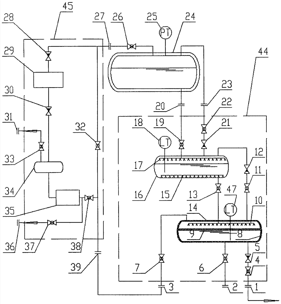
[0067] Embodiment 1: as figure 1As shown, the equipment of the replacement pressure delivery method for low-temperature liquefied gas includes a replacement unit (44), a BOG processing unit (45), and a low-temperature liquid storage tank (24). The low-temperature liquid storage tank (24) is used for storing low-temperature liquefied gas, and may be a low-temperature storage tank, a low-temperature tank car, or a low-temperature gas cylinder. The cryogenic liquid storage tank (24) is provided with a liquid phase port at least at the lowest part of the liquid phase, and a gas phase port, a BOG valve (26) port, and a low temperature liquid storage tank pressure display sensor (25) at the highest gas phase.

[0068] The replacement unit (44) includes a heat absorption tank (16) and a replacement tank (14). When the gas phase pressure of the tank is equal, the low-temperature liquid in the low-temperature liquid storage tank (24) can enter the heat-absorbing tank (16) under the ac...

Embodiment 2

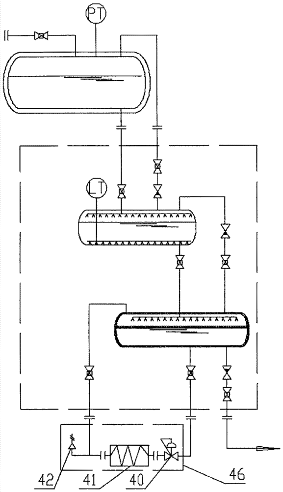
[0076] Embodiment 2: as figure 2 As shown, the self-pressurization unit (46) includes a self-supporting booster regulating valve (40), a booster gasifier (41) connected in sequence, and a gasifier safety valve (42) is provided on the communication pipeline.

[0077] The boost gasifier (41) is connected to the boost port (3); the self-supporting boost regulating valve (40) is connected to the boost liquid outlet (2).

[0078] When the self-pressurizing unit (46) is installed, the highest point should be lower than the lowest point of the displacement tank (14), and the ventilation should be good. It is beneficial that the low-temperature liquefied gas in the displacement tank (14) at a high place can enter the self-pressurization unit for gasification and pressurization under the action of its own weight. The self-supporting booster regulating valve (40) is an automatic pressure regulating valve, when the pressure in the displacement tank (14) is lower than the set pressure o...

Embodiment 3

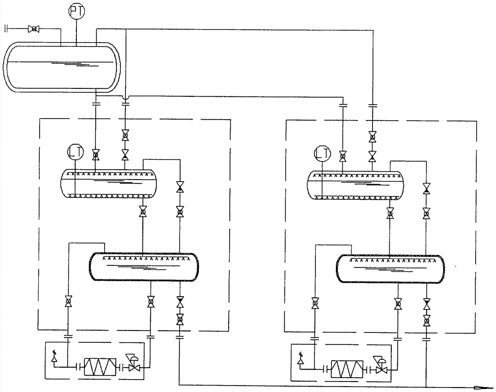
[0080] Example 3 as image 3 As shown, the replacement units (44) and the corresponding self-pressurizing units (46) can be used in parallel, and the work process of each basic replacement unit is alternately carried out at the same time by controlling (that is: there are One replacement unit (44) performs liquid filling process, one replacement unit (44) performs heat absorption and pressure reduction process, one replacement unit (44) performs gas-liquid replacement process, and one replacement unit (44) performs liquid discharge process) , to ensure that one of them performs the liquid discharge process at any time, which can realize the uninterrupted delivery of low-temperature liquefied gas to the outside. When the equipment with a large amount of liquid can also be provided with a buffer cryogenic storage tank (43) behind the discharge port (1) (such as Figure 4 ) to make gas or liquid supply more stable and reliable.

[0081] Others are with embodiment 2.


PUM


Abstract

The invention discloses a method and an apparatus for displacement type pressure conveying of a low-temperature liquefied gas. The method and the apparatus have the advantages that no low-temperature pump is needed for conveying the low-temperature liquefied gas to a high-pressure apparatus from a low-temperature liquefied gas, so that no energy is consumed, and a low-temperature storage tank also does not need to be supercharged and thus is prevented from overpressure and emission so that potential safety hazards and waste are prevented, and therefore, the energy source is saved and the ecological environment is protected. The apparatus comprises a displacement unit (44), a BOG (Boil Off Gas) treatment unit (45) and the low-temperature storage tank (24). The apparatus is low in apparatus investment, small in floor area, free of electric power, low in operation maintenance cost and high in safety.

Description

technical field [0001] The invention relates to the field of delivery of low-temperature liquefied gas, in particular, to a method and equipment with pumpless delivery. Such as liquid oxygen, liquid nitrogen, liquid argon, liquid hydrogen, liquid helium, liquefied natural gas (LNG) filling stations and filling stations, as well as gasification stations, LNG vehicle gas supply systems, etc. Background technique [0002] Cryogenic liquefied gas is a gas that exists in liquid form, and it is to cool down and liquefy the gas for the needs of storage and transportation. It has a low temperature (generally between -162°C and -256°C under normal pressure), a large gas-liquid ratio (that is, the volume ratio of a unit volume of low-temperature liquefied gas to gas that is vaporized into normal temperature and pressure), and high purity. Preservation is difficult (often due to poor thermal insulation performance of storage containers or production process requirements, gasification ...

Claims


Application Information

Patent Timeline
Patent Type & Authority Patents(China)
IPC IPC(8): F17D1/02F17D3/01F17D1/20
Inventor 张夏炎
Owner 北京奥尔克斯能源技术有限公司
Learn More