Damper opening and closing device
A technology of opening and closing device and air door, which is applied in the direction of transportation and packaging, heating/cooling equipment, air flow control components, etc. It can solve the problems of difficult to blow out air, large fluid pressure loss, etc., and achieve the effect of reducing pressure loss
- Summary
- Abstract
- Description
- Claims
- Application Information
AI Technical Summary
Problems solved by technology
Method used
Image
Examples
no. 1 example
[0068] Next, referring to the drawings, a damper opening and closing device according to a first embodiment will be described.
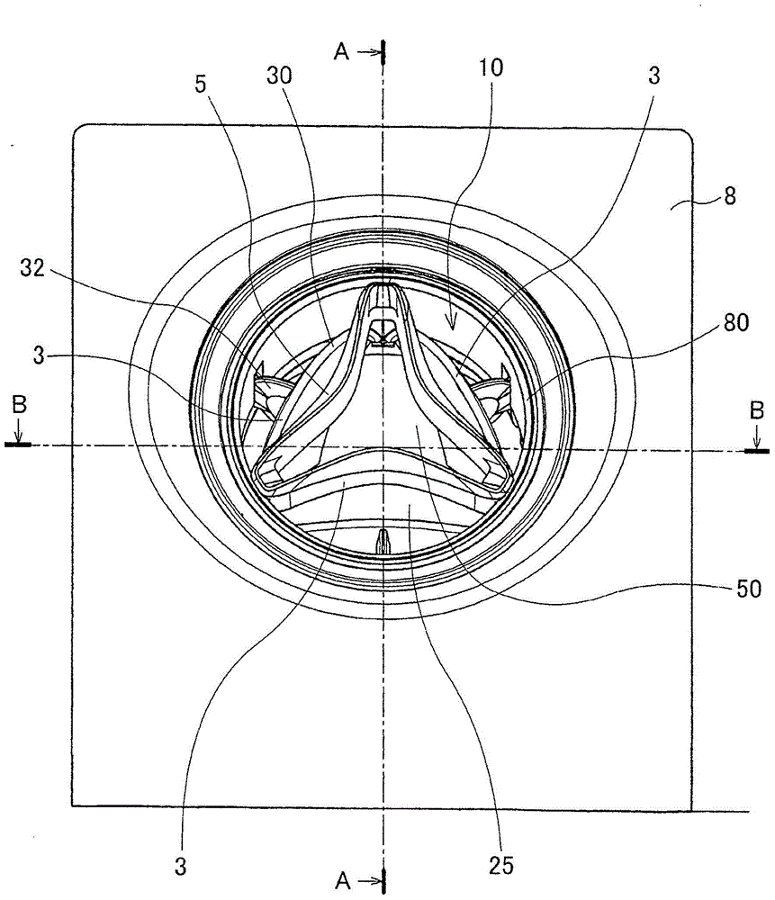
[0069] figure 1 It is a plan view showing the periphery of the air outlet 80 of the vehicle instrument panel 8 . Such as figure 1 As shown in , the damper opening and closing device 10 according to the first embodiment is provided in the air outlet 80 of the instrument panel 8 of the vehicle. The damper opening and closing device 10 includes a main body 25 and a holder 6 in which the main body 25 is pivotably held. The main body 25 includes an outer cylinder 1 , an inner cylinder 2 , a damper group 30 composed of a plurality of dampers 3 , and an operation part 5 .
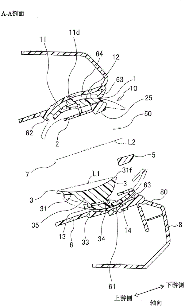
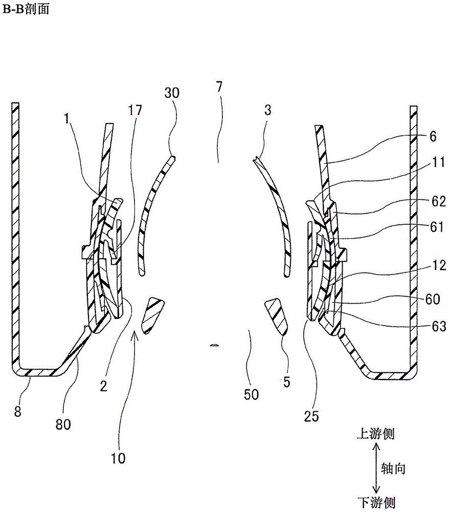
[0070] figure 2 is along figure 1 The cross-sectional view of arrow A-A in the middle, and, image 3 is along figure 1 Cross-sectional view of middle arrow B-B. Figure 4 It is an exploded perspective view of the damper opening and closing device 10 . Such as figure 2 As ...
no. 2 example
[0103] Such as Figure 13 and Figure 14 As shown in , three rectifying fins 51 are radially arranged in the center of the operation portion 5 . In addition, the arc-shaped fin portion 38 protrudes from the inner surface of the damper body 31 of each damper 3 toward the central axis of the flow path 7 . Seen from the air outlet 80 on the downstream side, the rectifying fins 51 of the operating portion 5 and the fin portions 38 of the damper 3 are alternately arranged at equal intervals in the circumferential direction. The rectifying fins 51 and the fin portion 38 have a thin plate shape, and are arranged in the axial direction. The air conditioning air 70 flowing through the flow channel 7 is rectified by the rectifying fins 51 and the fin portion 38 , and then blown out through the air outlet 80 . Accordingly, the rectification effect of the air-conditioning wind is good.
no. 3 example
[0105] In the third embodiment, the semicircular portion 35 protrudes from the outer surface of the damper main body 31, such as Figure 15 and Figure 16 shown in . A gear 39 constituted by a helical gear is formed on the outer peripheral edge of the semicircular portion 35 . The semicircle 35 fits into the cutout 24 formed in the inner barrel 2 . A rack 19 constituted by an internal gear is formed on the inner peripheral surface of the outer cylinder 1, and the rack 19 is provided continuously over the entire circumferential direction thereof. The gear 39 of the damper 3 is meshed with the rack 19 of the outer tube 1 . When the inner tube 2 is rotated by the operation of the operation part 5 , the gear 39 of the damper 3 is moved along the tooth groove axis of the rack 19 . The damper 3 swings around the support portion 32 through the axial movement of the gear 39 , and opens and closes the flow channel 7 . The gear 39 and the rack 19 constitute an angle control device ...
PUM
 Abstract
Description
Claims
Application Information
 - R&D
- Intellectual Property
- Life Sciences
- Materials
- Tech Scout
- Unparalleled Data Quality
- Higher Quality Content
- 60% Fewer Hallucinations
Browse by: Latest US Patents, China's latest patents, Technical Efficacy Thesaurus, Application Domain, Technology Topic, Popular Technical Reports.
© 2025 PatSnap. All rights reserved.Legal|Privacy policy|Modern Slavery Act Transparency Statement|Sitemap|About US| Contact US: help@patsnap.com


