Phase extraction method and detecting device for single width carrier frequency interference fringes

A technology of interference fringes and phase extraction, applied in the field of optical measurement, which can solve the problems of inability to achieve quantification and low cost.

Active Publication Date: 2014-08-27
SHANGHAI INST OF OPTICS & FINE MECHANICS CHINESE ACAD OF SCI
View PDF6 Cites 34 Cited by
  • Summary
  • Abstract
  • Description
  • Claims
  • Application Information

AI Technical Summary

Problems solved by technology

[0005] The purpose of the present invention is to solve the problem of quantitative, high-efficiency, and low-cost testing in the process of process detection in the process of pla

Method used


Image

  • Phase extraction method and detecting device for single width carrier frequency interference fringes
  • Phase extraction method and detecting device for single width carrier frequency interference fringes
  • Phase extraction method and detecting device for single width carrier frequency interference fringes

Examples


Embodiment Construction

[0049] The present invention will be further described below in conjunction with drawings and embodiments.

[0050] The method of the present invention for phase extraction of a single carrier frequency interference fringe detected by a large planar optical element comprises the following steps:

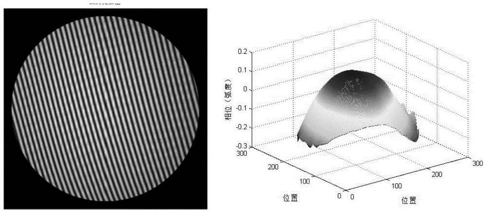
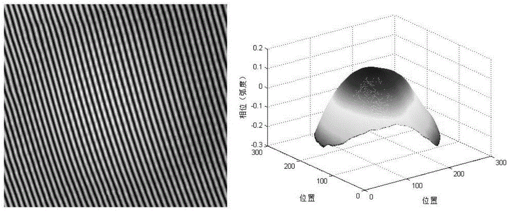
[0051] The first step is to use a solid-state imaging device to obtain a carrier-frequency interference fringe image formed by interference between the measured surface shape of the optical element and the surface shape of the standard optical element, and convert it into the first digital interference fringe image through the A / D converter; use the adaptive The histogram equalization method enhances the contrast of the first digital interference fringe image to obtain the second digital interference fringe image, such as figure 1 Shown on the left. Using the sample-based block reconstruction method (A.Criminisi, RegionFilling and Object Removal by Exemplar-Based Image Inpainting, I...


PUM


Abstract

Provided are a phase extraction method and a detecting device for single width carrier frequency interference fringes. The phase extraction method and the detecting device are used for large plane optical element detection. The method is mainly based on virtual grating phase shifting moire fringes and two-dimensional Fourier transformation, two-dimensional wave surface phase information of a detected optical element is extracted from a single carrier frequency interference pattern within a full aperture range, and a computing method for a GRMS value of a circular aperture component surface shape is put forward. In addition, the plane optical element surface shape detecting device constructed on the basis of the method can be applied to procedure interference detection of optical manufacturing workshops. According to the phase extraction method and the detecting device, the requirement for detection of plane optical element transmission/reflection low frequency surface shape deviation can be met, and precision and efficiency of manufacturing detecting are improved.

Description

technical field [0001] The present invention relates to optical measurement, in particular to a single carrier frequency interference fringe phase extraction method and detection device for the detection of large planar optical elements, which are mainly used in large planar optics required by large-scale laser fusion devices, military industry, aerospace and other fields Process inspection during component processing. Background technique [0002] In the large-aperture planar optical element processing workshop, due to the limitation of the workshop environment, high-precision digital phase-shifting interferometer cannot be used for the detection of the transmission / reflection surface shape of the optical element, but it is suitable for the existing commercial Interferometers, such as dynamic interferometers and transient carrier frequency method interferometers, are relatively expensive, which is not conducive to the reduction of optical processing costs, and there is no c...

Claims


Application Information

Patent Timeline
IPC IPC(8): G01B11/25
Inventor 周游刘世杰白云波陈惟肖王微微
Owner SHANGHAI INST OF OPTICS & FINE MECHANICS CHINESE ACAD OF SCI
Why Eureka
Try Eureka