Eureka AIR delivers breakthrough ideas for toughest innovation challenges, trusted by R&D personnel around the world.

Optical fiber Ethernet intelligent branching unit switching method based on FPGA

A technology of Ethernet and splitter, applied in the field of network security, can solve problems such as single function, single function, no internal data packet information statistics function and automatic switching, etc., to achieve the effect of ensuring communication quality

Inactive Publication Date: 2014-08-27
SOUTH CHINA UNIV OF TECH
View PDF5 Cites 18 Cited by
  • Summary
  • Abstract
  • Description
  • Claims
  • Application Information

AI Technical Summary

Problems solved by technology

The shortcomings and deficiencies of the existing technology mainly include: the function is relatively single, usually a single link processing; the electrical interface equipment cannot be serialized into the optical fiber backbone network and the backup processing of key equipment through a single system; at the same time, it is not intelligent enough, and there is no internal data packet Information statistics function and automatic switching function

Method used


Image

  • Optical fiber Ethernet intelligent branching unit switching method based on FPGA
  • Optical fiber Ethernet intelligent branching unit switching method based on FPGA
  • Optical fiber Ethernet intelligent branching unit switching method based on FPGA

Examples


Embodiment

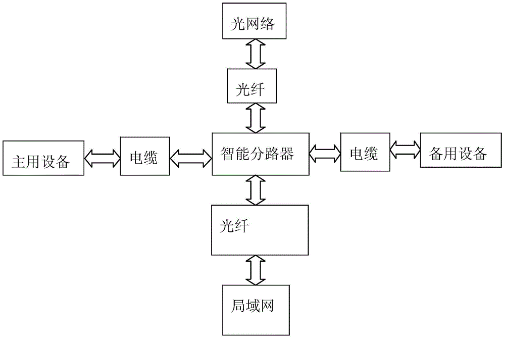
[0039] Such as figure 1 As shown, the entire working scenario is: the front end of the intelligent splitter is connected to the external optical network, the main device and the backup device are connected in the middle, and the rear end is connected to the LAN through optical fiber. Under normal circumstances, the main device is connected to the network. Once the main device fails or the bit error rate exceeds a certain threshold, switch to the backup device and use the backup device to communicate. The system can still work uninterrupted. Thereby ensuring that the network will not be paralyzed due to the failure of a single device.

[0040] A switching system based on the switching method of the FPGA-based optical fiber Ethernet intelligent splitter has the following effects:

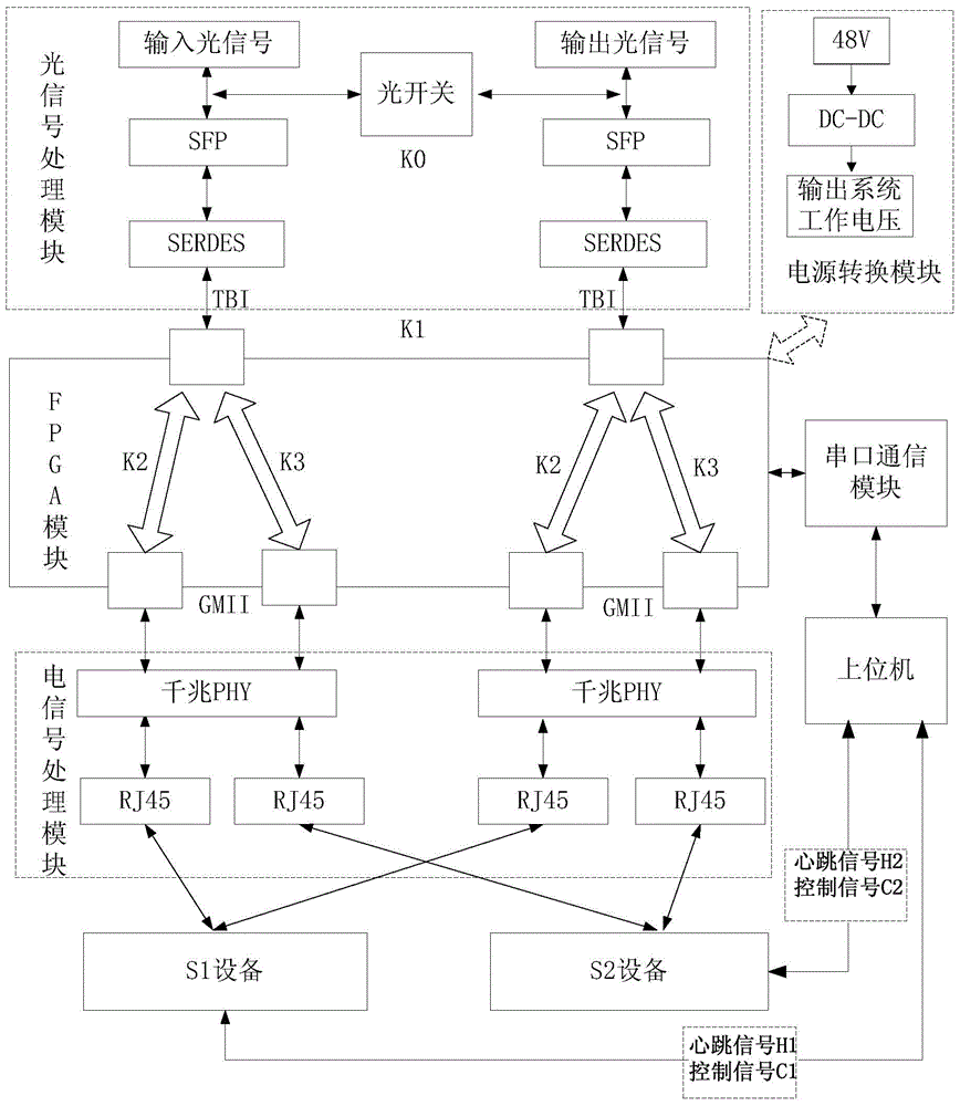
[0041] 1. Photoelectric signal processing: convert the optical signal from the external optical network into an electrical signal, and the optical signal is connected to the FPGA in the TBI data form...


PUM


Abstract

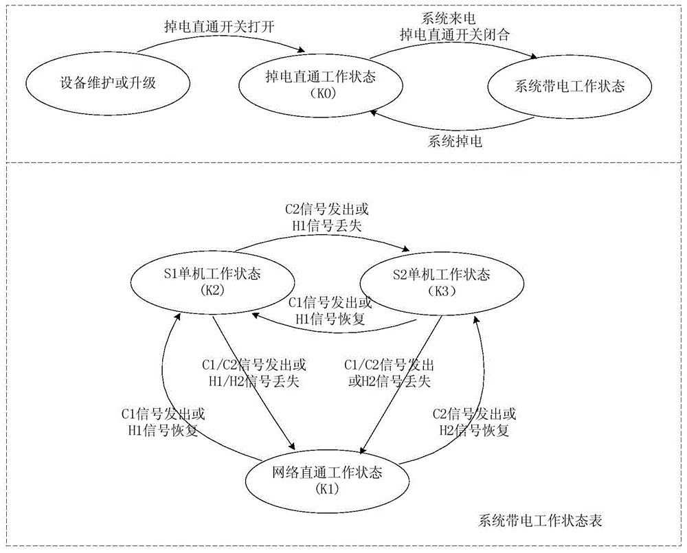
The invention discloses an optical fiber Ethernet intelligent branching unit switching method based on an FPGA. The method includes the following steps that first, the current working state of an optical fiber Ethernet intelligent branching unit is set to be a main-use link state K2; second, when a main-use device breaks down or the bit error rate of the optical fiber Ethernet intelligent branching unit exceeds a set threshold value, the third step is executed, and otherwise, the first step is executed; third, the working state of the optical fiber Ethernet intelligent branching unit is switched to be a standby link state K3 through an active switching mode or a passive switching mode; fourth, when faults of the main-use device are removed and the bit error rate of the optical fiber Ethernet intelligent branching unit is within the set threshold value range, the current working state of the optical fiber Ethernet intelligent branching unit is switched to the main-use link state K2 from the standby link state K3; fifth, the first step, the second step, the third step and the fourth step are repeatedly executed. The method has the advantages that the stability of key network equipment can be maintained, and the defects in an original single technology application are overcome.

Description

technical field [0001] The invention relates to a network security technology, in particular to a switching method of an FPGA-based optical fiber Ethernet intelligent splitter. Background technique [0002] With the continuous advancement of informatization construction, the informatization of enterprises has become very common. The activities of various enterprises and institutions rely more and more on their key business information systems. These business information systems play an important role in the operation and development of the entire organization. critical use. If some key equipment fails or applications stop, it will bring huge economic losses to the enterprise, and the reputation of the enterprise will be affected due to the unavailability of the business, causing customers to lose trust in the enterprise, and the harm caused is fatal . At the same time, at present, most enterprises and institutions directly use optical fiber as the transmission medium to es...

Claims


Application Information

Patent Timeline
Patent Type & Authority Applications(China)
IPC IPC(8): H04L12/24H04L12/26
Inventor 贺前华宋伟
Owner SOUTH CHINA UNIV OF TECH
Why Eureka
Eureka Blog
Learn More