Positive-locking clutch

A technology of clutches and mating teeth, which is applied in the direction of clutches, magnetic drive clutches, non-mechanical drive clutches, etc., to achieve the effect of simplifying opening

Active Publication Date: 2014-08-27
MAGNA POWERTRAIN AG & CO KG
View PDF7 Cites 2 Cited by
  • Summary
  • Abstract
  • Description
  • Claims
  • Application Information

AI Technical Summary

Problems solved by technology

However this leads to the fact that the performance of the clutch must be designed for possibly high torques, as can occur at the drive shaft

Method used


Image

  • Positive-locking clutch
  • Positive-locking clutch
  • Positive-locking clutch

Examples


Embodiment Construction

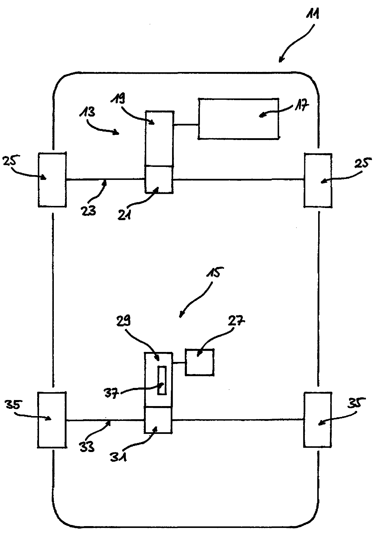
[0037] exist figure 1 The motor vehicle 11 is shown in a schematic illustration. The motor vehicle 11 has two drive trains 13 , 15 , one of which 13 has an internal combustion engine 17 as drive, which drives an axle with wheels 25 via a transmission 19 and an axle differential 21 twenty three. In the embodiment shown here, the axle 23 is the front axle of the motor vehicle 11 . The other drive train 15 includes an electric motor 27 as drive, which is connected to an intermediate transmission 29 . The intermediate transmission 29 is connected on the output side to an axle differential 31 which forms the main transmission for the drive train 15 and can transmit torque to the axle 33 and to the wheels 35 . Furthermore, a clutch 37 is provided in the intermediate transmission 29 .

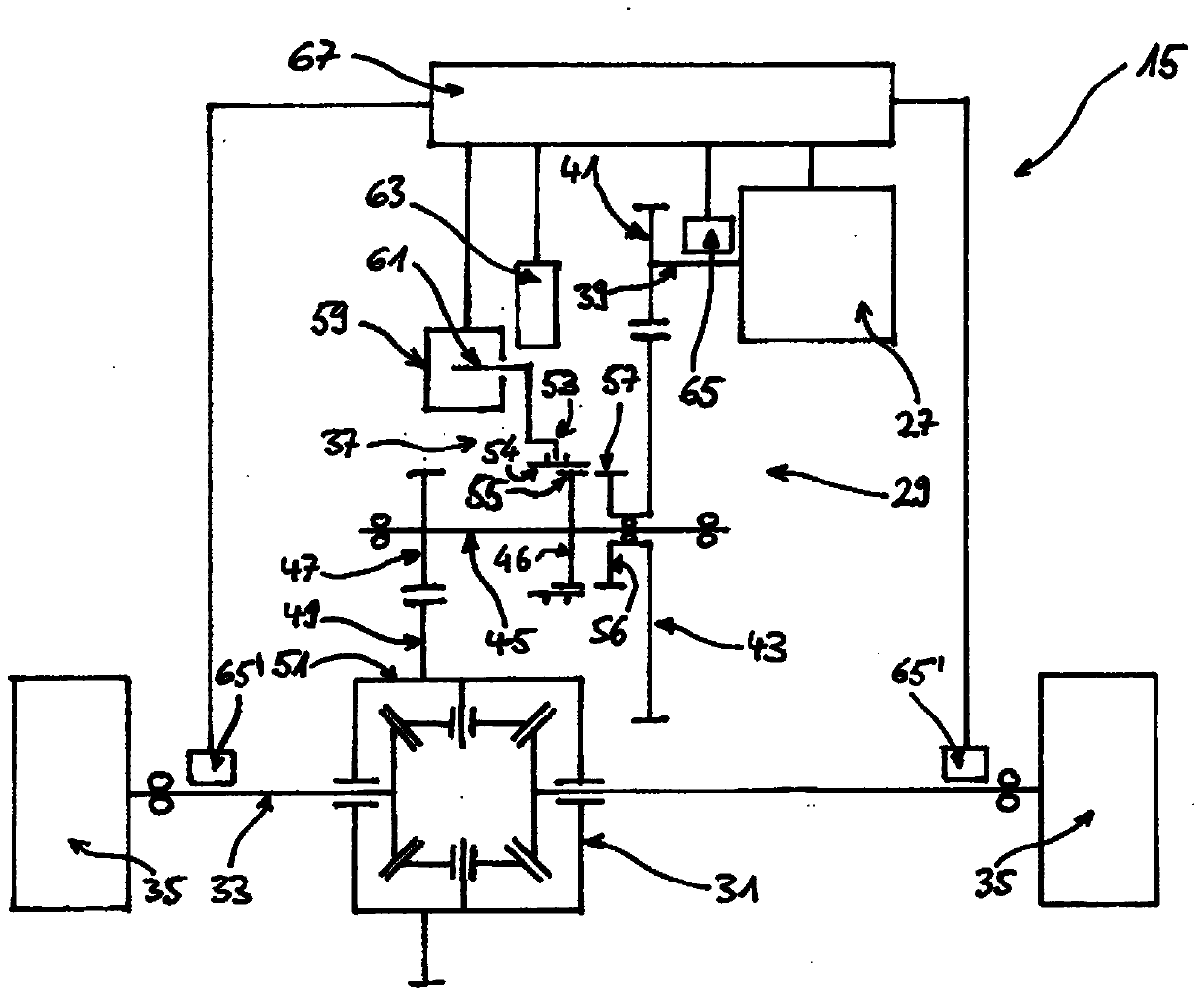
[0038] figure 2 The schematic illustration in FIG. 3 shows drive train 15 with electric motor 27 , intermediate transmission 29 and a main transmission designed as axle differential 31 . The wh...


PUM


Abstract

A positive-locking clutch (37) for a motor vehicle (11) comprises a coupling element (53) with toothing (54), a rotatable counterpart element (56) with counterpart toothing (57) and an electromagnetic actuator (59). The coupling element (53) can be moved by means of the electromagnetic actuator (59) between a disengaged position and an engaged position, wherein the toothing (54) of the coupling element (53) is meshed with the counterpart toothing (57) of the counterpart element (56) in the engaged position. A circumferential backlash is provided between the toothing (54) of the coupling element (53) and the counterpart toothing (57) of the counterpart element (56), even after the engaged position of the coupling element (53) has been fully reached.

Description

technical field [0001] The invention relates to a form-fitting clutch for a motor vehicle, comprising a coupling element with toothing, a rotatable counter element with mating toothing and an electromagnetic actuator, wherein the coupling element is The electromagnetic actuator is adjustable between a disengaged position and an engaged position, and wherein in the engaged position the toothing of the coupling element engages with the mating toothing of the mating element. Furthermore, the invention relates to a drive train of a motor vehicle having such a clutch. Background technique [0002] Motor vehicles with hybrid drives are known, in which one drive shaft is driven by an internal combustion engine and the other drive shaft can be driven by an electric motor. The drive of the motor vehicle via the electric motor is generally not permanent, but selective and adapted to the respective driving situation. Typically, the electric motor drive is switched on during accelerat...

Claims


Application Information

Patent Timeline
Patent Type & Authority Applications(China)
IPC IPC(8): F16D48/06F16D27/118
CPCY10T477/327F16D2500/50607F16D27/09F16D2500/10462B60W10/08F16D48/064F16D2500/30408F16D27/118B60W10/02
Inventor 大卫·维拉姆多米尼克·舍贝尔丹尼尔·普里马库斯·科尔伯克
Owner MAGNA POWERTRAIN AG & CO KG
Why Eureka
Try Eureka