
Equipment for continuously welding circular welds

A technology of annular welding seam and equipment, applied in the field of annular welding equipment, can solve the problems of unsatisfactory welding effect, porosity, virtual welding, etc.

Inactive Publication Date: 2014-09-03
丹阳市长江汽车部件有限公司
View PDF0 Cites 19 Cited by
  • Summary
  • Abstract
  • Description
  • Claims
  • Application Information

AI Technical Summary

Problems solved by technology

Different shapes require different tooling, and the welding effect is not ideal, which is prone to defects such as virtual welding and air holes, and causes a lot of waste of materials

Method used


Image

  • Equipment for continuously welding circular welds
  • Equipment for continuously welding circular welds

Examples


Embodiment Construction

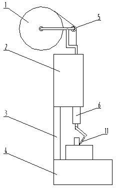
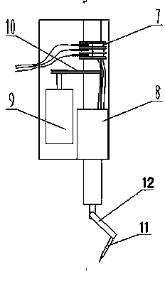
[0009] Depend on figure 1 Known, a kind of equipment of uninterrupted welding annular weld, consists of welding wire winch 1, hydraulic power control cabinet 2, column 3, workbench 4, welding wire guide wheel 5, welding torch main shaft 6, electric slip ring 7, hydraulic cylinder 8, motor 9. The belt 10 and the welding torch head 11 are composed of the welding wire winch 1, the welding wire guide wheel 5 and the welding torch head 11 are installed on the welding torch main shaft 6 in the hydraulic power control cabinet 2, and the hydraulic power control cabinet 2 and the workbench 4 are fixed by the column 3 Together, 7 electric slip rings, 8 hydraulic cylinders, 9 motors, and belts 10 are the main electric hydraulic components inside the hydraulic power control cabinet 2. During work, the workpiece is fixed on the workbench, the power supply motor 9 drives the welding torch main shaft 6 to rotate through the belt 10, and the rotation of the welding wire and the welding torch ...


PUM


Abstract

Equipment for continuously welding circular welds is composed of a welding wire winch (1), a hydraulic power control cabinet (2), a stand column (3), a workbench (4), a welding wire guide wheel (5), a welding torch main shaft (6), an electric slip ring (7), a hydraulic cylinder (8), a motor (9), a belt (10) and a welding torch head (11). The equipment for continuously welding circular welds is characterized in that the welding torch main shaft (6) is connected with a belt pulley, the motor (9) drives the welding torch main shaft (6) to rotate via the belt (10), the hydraulic cylinder (8) compresses a workpiece, a power source is switched on, the welding torch head (11) rotates according to a track circle set by a telescopic rod (12), and then circular welds of different diameters are welded. The equipment for continuously welding circular welds can meet the welding requirement of welds of different diameters, manual intervention is not required in the rotation welding process, and the equipment can continuously rotate by 360 degrees and is free of power interruption.

Description

technical field [0001] The invention relates to a ring type welding equipment. Especially when it comes to the welding needs of products that require ring welding. Background technique [0002] With the advancement of science and technology, one after another large-scale equipment is designed and manufactured. Projects that cannot be completed by manpower are easily completed by these large-scale equipment. The reason why these large-scale equipment can have such power is the result of the cooperation of individual components. These parts are produced due to different materials and different performances. The way it is processed is also different. In the past, the welding process had to be operated manually, and the current was adjusted based on experience. The welding speed was slow and the welding quality was poor. When encountering regular circular welds, it is necessary to make corresponding tooling. Different shapes require different tooling, and the welding effec...

Claims


Application Information

Patent Timeline
IPC IPC(8): B23K9/133B23K9/028
CPCB23K9/028B23K9/125B23K9/287
Inventor 聂顺康陆宇锋
Owner 丹阳市长江汽车部件有限公司
Learn More