A multi-line delivery system and method for a multi-stage pumping station slurry pipeline

A technology for pipeline transportation and pumping stations, which is applied in the pipeline system, gas/liquid distribution and storage, mechanical equipment, etc. It can solve the problems of low utilization rate, high cost and large environment of the slurry pipeline transportation system, and improve the transportation efficiency and economic benefits, improve utilization, and improve the effect of conveying output

Active Publication Date: 2016-06-15
YUNNAN DAHONGSHAN PIPELINE
View PDF5 Cites 0 Cited by
  • Summary
  • Abstract
  • Description
  • Claims
  • Application Information

AI Technical Summary

Problems solved by technology

With the continuous lengthening of the slurry pipeline distance, a slurry pipeline transportation system based on multi-stage pumping stations appears, and the slurry pipeline needs to transport a variety of different grades of pulp such as iron ore concentrate, which cannot be compared due to the different grades For example, there are two kinds of iron ore concentrate produced by the Dahongshan Concentrator: the first is the iron ore concentrate with a grade of 60% to 65% (referred to as 61 grade I concentrate), and the second The first type is iron concentrate with a grade of 52% to 60% (referred to as 56 grade No. Ⅱ concentrate). The traditional transportation method is to transport No. 1 concentrate through the existing slurry pipeline. Low-cost transportation by means of land vehicles such as automobiles. This transportation method has high costs, and automobile transportation will bring greater environmental pollution, and the utilization rate of the existing slurry pipeline transportation system is low. How to base on the existing multi-stage The multi-pipeline transportation of various grades of pulp in the slurry pipeline system of the pumping station is of great significance to promote the development of the slurry pipeline transportation system, reduce pipeline transportation costs, and improve efficiency

Method used


Image

  • A multi-line delivery system and method for a multi-stage pumping station slurry pipeline

Examples


Embodiment Construction

[0023] The technical solution of the present invention will be described in detail below in conjunction with the accompanying drawings, so that those skilled in the art can understand the present invention more clearly, but the protection scope of the present invention is not limited thereby.

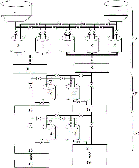
[0024] combined with figure 1As shown, the multi-stage pumping station slurry pipeline multi-line delivery system of the present invention is preferably a double-pipeline delivery system based on a three-stage pumping station, including a first-stage pumping station A, a second-stage pumping station B, and a third-stage pumping station. Pumping station C, the first-level pumping station A is used as a concentrated treatment pumping station for different grades of ore produced by the upper-level dressing plant, including a first pipeline delivery unit and a second pipeline delivery unit, wherein the first pipeline delivery unit includes the first Thickening tank 1, stirring tank 3 and st...


PUM


Abstract

The present invention proposes a multi-stage pumping station slurry pipeline multi-pipeline delivery system and method, the delivery system at least includes a first-stage pumping station, a second-stage pumping station and a third-stage pumping station, each pumping station includes More than two pipeline delivery units, each pipeline delivery unit includes a stirring tank and a main pump, and different pipeline delivery units of adjacent two-stage pumping stations can switch to each other to form a multi-pipeline delivery path. The delivery method includes Steps: 1), transport the different grades of pulp delivered by the concentrator to different thickening tanks in the first-stage pumping station; 2), for each grade of pulp, select the pipelines in the pumping stations at all levels The conveying unit transports the ore slurry to the predetermined dehydration station. The invention realizes the slurry transportation based on the sharing of the mixing tank among the multi-stage pumping stations and the mutual switching of the transportation pipelines, and can simultaneously carry out the transportation of various grades of pulp, which greatly improves the transportation efficiency of the slurry pipeline system and reduces the impact on the environment. pressure.

Description

technical field [0001] The invention relates to the technical field of slurry pipeline transportation, and more particularly relates to a multi-stage slurry pipeline multi-line transportation system and method of a multi-stage pumping station. Background technique [0002] Slurry pipeline transportation technology belongs to the high-tech industry. It is different from traditional transportation methods such as roads, railways, water transportation, and aviation. Slurry pipeline transportation not only has large transportation volume, continuous, rapid, economical, safe, reliable, stable and low investment It has unique advantages such as less land and low cost, and can realize automatic control. With the continuous lengthening of the slurry pipeline distance, a slurry pipeline transportation system based on multi-stage pumping stations appears, and the slurry pipeline needs to transport a variety of different grades of pulp such as iron ore concentrate, which cannot be comp...

Claims


Application Information

Patent Timeline
Patent Type & Authority Patents(China)
IPC IPC(8): F17D1/14
Inventor 王长勇普光跃白建民潘春雷瞿承中马波孔垂洪
Owner YUNNAN DAHONGSHAN PIPELINE
Why Eureka
Try Eureka