Supercharge Your Innovation With Domain-Expert AI Agents!

Optical fiber micro-bending sensor with serialized cushion structure

A microbend sensor and optical fiber technology, which is applied in the direction of measuring the change of optical properties of materials when they are stressed, can solve the problems of small measurement range and optical fiber damage, and achieve the purpose of preventing additional bending of optical fibers, stable loading, and resistance to fiber. The effect of strong interference ability

Active Publication Date: 2014-09-03
HEILONGJIANG INST OF TECH
View PDF8 Cites 5 Cited by
  • Summary
  • Abstract
  • Description
  • Claims
  • Application Information

AI Technical Summary

Problems solved by technology

[0005] The present invention aims to solve the problem that the existing optical fiber microbend sensor has a small measurement range and the optical fiber is easily damaged, and provides a serialized cushion structure optical fiber microbend sensor

Method used


Image

  • Optical fiber micro-bending sensor with serialized cushion structure
  • Optical fiber micro-bending sensor with serialized cushion structure

Examples


specific Embodiment approach 1

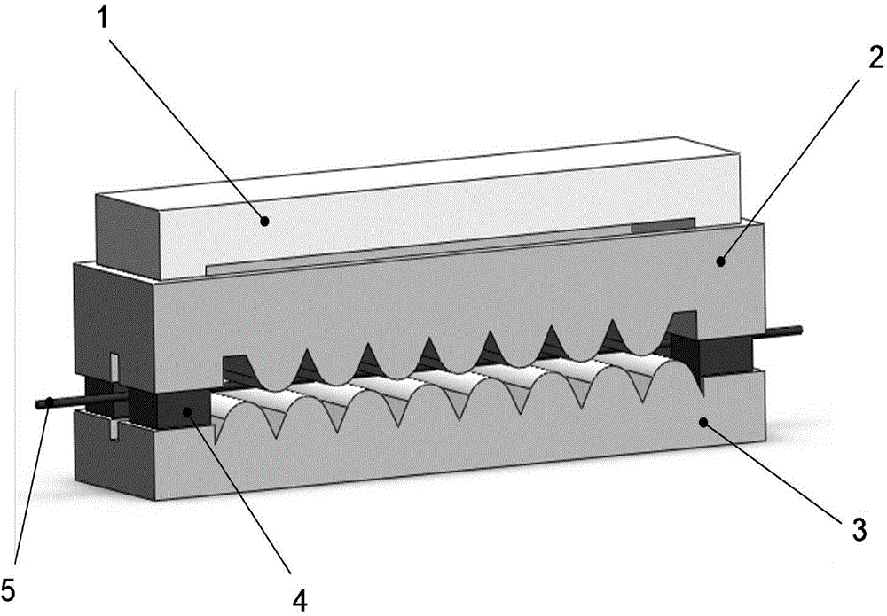
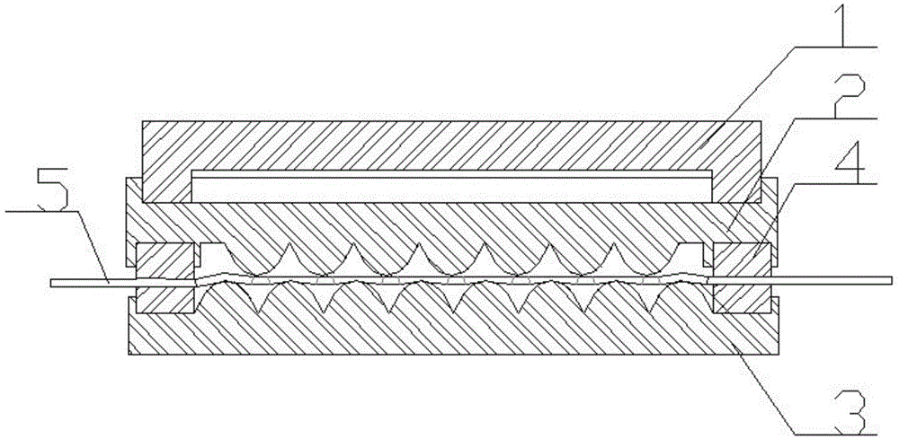
[0015] Specific implementation mode one: as figure 1 , figure 2 As shown, the serialized cushion structure optical fiber microbend sensor of the present embodiment includes a loading bridge 1, an upper toothed plate 2, a lower toothed plate 3, four pads 4 and an optical fiber 5; the upper toothed plate 2 There is a reserved groove on the upper end surface, and the lower end surface of the loading bridge 1 is set in the reserved groove; the lower end surface of the upper toothed plate 2 is provided with seven upper teeth with a semicircular cross-section along the length direction. The lower end surfaces of the four corners of the upper toothed plate 2 are respectively provided with square protrusions, and an optical fiber channel is arranged between the two square protrusions on the same side in the width direction, and on the lower end surfaces of the four corners of the square protrusions All have square grooves; the upper end surface of the lower toothed plate 3 is provid...

specific Embodiment approach 2

[0018] Embodiment 2: The difference between this embodiment and Embodiment 1 is that the loading bridge 1 is made of LY12 superhard aluminum alloy. Others are the same as the first embodiment.

specific Embodiment approach 3

[0019] Embodiment 3: This embodiment differs from Embodiment 1 or Embodiment 2 in that: the upper toothed plate 2 is processed by LY12 superhard aluminum alloy. Others are the same as those in Embodiment 1 or 2.


PUM


Abstract

The invention relates to an optical fiber micro-bending sensor with a serialized cushion structure, aiming to solve the problems of an existing optical fiber micro-bending sensor that the measurement range is small and an optical fiber is easy to damage. The serialized cushion structure optical fiber micro-bending sensor comprises a loading bridge, an upper tooth-shaped plate, a lower tooth-shaped plate, four cushion blocks and an optical fiber, wherein a pre-formed groove is formed in the upper end face of the upper tooth-shaped plate; the lower end face of the loading bridge is arranged in the pre-formed groove; the upper tooth-shaped plate comprises seven upper teeth; the lower tooth-shaped plate comprises eight lower teeth; the upper teeth are matched with lower teeth so that the optical fiber is micro-bent when penetrating out from an optical fiber channel at one side to an optical fiber channel at the other side. The optical fiber micro-bending sensor is used for force measurement.

Description

technical field [0001] The invention relates to a serialized cushion structure optical fiber microbend sensor. Background technique [0002] There are many methods for measuring pressure in traditional pressure sensors, such as strain gauge measurement, optical measurement, Hall effect measurement, grating ruler measurement and so on. However, many current measurement methods are not conducive to remote measurement and monitoring, especially due to the interference of strong external electrical signals, serious distortion of remote transmission, complex measurement mechanism, poor reliability, and unfavorable maintenance. In addition, for flammable and explosive environments, all methods of using electrical measurement are not suitable, because any spark may cause serious fire or explosion accidents, causing immeasurable losses. The optical fiber stress sensor has many advantages and has attracted people's attention. For example, the fiber grating stress sensor has been st...

Claims


Application Information

Patent Timeline
IPC IPC(8): G01L1/24
Inventor 莫淑华王国星王丽雪尹志娟仵辉勇于东
Owner HEILONGJIANG INST OF TECH
Features
  • R&D
  • Intellectual Property
  • Life Sciences
  • Materials
  • Tech Scout
  • Unparalleled Data Quality
  • Higher Quality Content
  • 60% Fewer Hallucinations
Learn More