
Bearing Torque Test Device

A technology for torque testing and bearings, which is applied in the field of bearing torque testing devices, can solve problems such as insufficient simulation of bearing friction torque, inability to affect measurement accuracy, complex and large structure, etc., and achieve the effect of easy sampling and in-situ observation, and simple structure

Inactive Publication Date: 2017-06-06
TSINGHUA UNIV
View PDF9 Cites 0 Cited by
  • Summary
  • Abstract
  • Description
  • Claims
  • Application Information

AI Technical Summary

Problems solved by technology

For example, the patent No. 201110417343.4 discloses a horizontal bearing friction torque measuring device with a horizontal structure, and realizes loading in two directions at the same time, which can more closely simulate the actual working conditions of the bearing; for example, the patent No. 201310517828.X Disclosed is a test device and method for friction torque under actual working conditions of bearings. Using the characteristics of the micro-friction torque of the air flotation platform to test the friction torque under actual working conditions (different preloads) of bearings, it solves the problem of existing bearing friction. The technical problem that the torque testing instrument cannot fully simulate the friction torque of the bearing in the actual working condition
[0004] Although the test equipment in the above disclosed patents can further simulate the actual working conditions of the bearings, most of the bearing test benches have complex and large structures at present, and are not easy to disassemble, which affects the measurement accuracy and cannot perform in-situ inspection of the lubricant in the bearing after work. sampling

Method used


Image

  • Bearing Torque Test Device
  • Bearing Torque Test Device
  • Bearing Torque Test Device

Examples


Embodiment Construction

[0016] The bearing torque testing device provided by the present invention will be further described in detail below in conjunction with the accompanying drawings and specific embodiments.

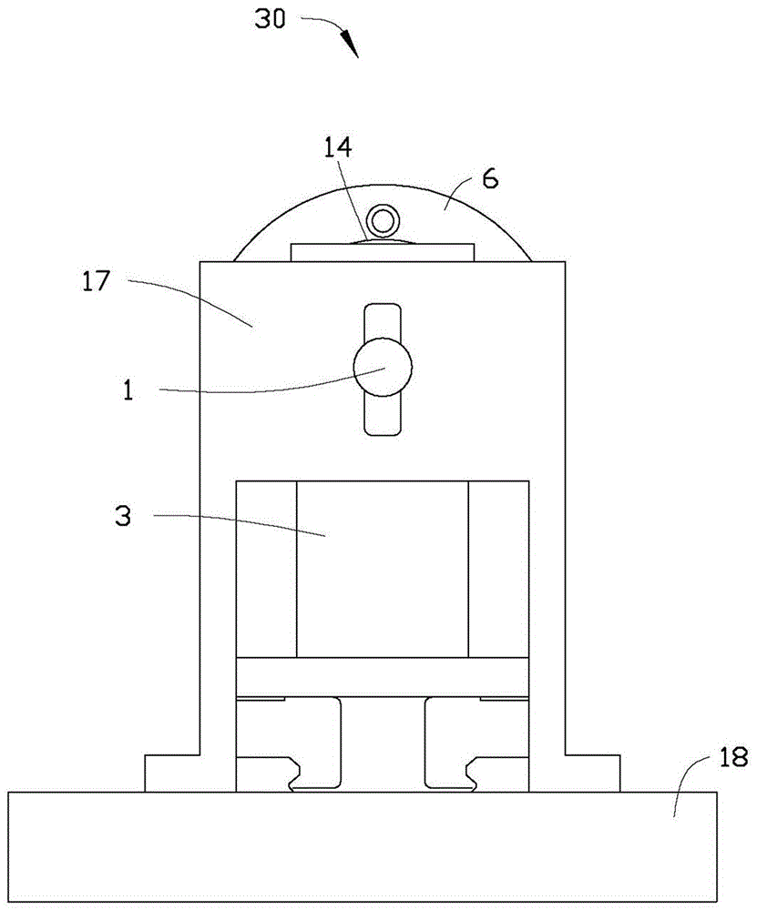
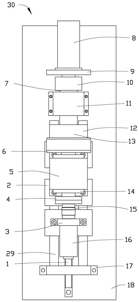
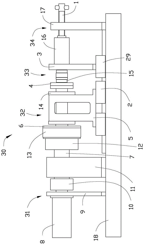
[0017] see Figure 1 to Figure 3 The bearing torque testing device 30 includes a driving unit 31 , a testing unit 32 , an online observation unit 33 , a loading unit 34 , a bottom plate 18 , a first sliding guide rail 2 , and a second sliding guide rail 29 . The drive unit 31 is fixed on the base plate 18, the test unit 32 is connected to the drive unit 31, and a part of the test unit 32 is fixed on the base plate 18, and a part is arranged on the base plate 18 through the first sliding guide rail 2. Base plate 18, the online observation unit 33 is connected between the test unit 32 and the loading unit 34, a part of the loading unit 34 is arranged on the base plate 18 through the second sliding guide rail 29, and a part is fixed on the base plate 18 .

[0018] The drive unit 31 includes...


PUM


Abstract

The invention relates to a bearing torque testing device which comprises a bottom plate, a drive unit, a testing unit, an on-line observation unit and a loading unit. The drive unit is fixedly arranged on the bottom plate. The testing unit is connected to the drive unit, and is powered by the drive unit. The on-line observation unit comprises a sensor, and one end of the sensor is connected with the testing unit. The loading unit is connected with the other end of the sensor and is used for loading a tested bearing.

Description

technical field [0001] The invention relates to a bearing torque testing device, in particular to a bearing torque testing device capable of bearing axial load. Background technique [0002] Bearings are indispensable key components in various fields of aviation, heavy industry and advanced manufacturing equipment. According to statistics, about 90% of the bearings currently in use are lubricated with grease. Grease lubrication has incomparable advantages over oil lubrication, namely low friction coefficient, low consumption and no need for additional circulation supply devices. In most cases, grease-lubricated bearings have a longer re-greasing cycle, which greatly reduces manufacturing and operation and maintenance costs as well as energy consumption. The mechanism of grease lubrication is very different from oil lubrication, and grease is more suitable for harsh working conditions such as heavy load and high temperature. Extremely harsh working conditions will lead to ...

Claims


Application Information

Patent Timeline
Patent Type & Authority Patents(China)
IPC IPC(8): G01M13/04
Inventor 郭丹黄鹭温诗铸雒建斌
Owner TSINGHUA UNIV
Learn More