
Two-position six-way reversing valve for pressure-regulating suspended mass sampler

A suspended mass sampler, two-position six-way technology, applied in the direction of sampling devices, etc., can solve problems such as complex structure, long pressure regulation time, easy breakage of gear teeth, etc., and achieve simple driving mechanism, extended working life, and sealing pressure adjustable effect

Inactive Publication Date: 2016-06-29
XIHUA UNIV
View PDF5 Cites 0 Cited by
  • Summary
  • Abstract
  • Description
  • Claims
  • Application Information

AI Technical Summary

Problems solved by technology

The two-way sampler has the problem of too long pressure regulation time and nozzle sand accumulation, the three-way sampler solves the problem of too long pressure regulation time, and the four-way sampler basically solves the problem of long pressure regulation time and nozzle sand accumulation
There are major defects in this rotary valve structure: first, the structure is complex, the failure rate is high, and maintenance is difficult; The volume of the valve is limited, the teeth of the driving gear are easily broken, the transmission chain is damaged, and the switch valve is invalid; the fourth is that the seal is not reliable, the motor is prone to water ingress and malfunction, and the reliability is low
From the perspective of usage, many problems of the above on-off valves lead to the inability of the sampler to sample accurately, which has brought troubles to the hydrological department

Method used


Image

  • Two-position six-way reversing valve for pressure-regulating suspended mass sampler
  • Two-position six-way reversing valve for pressure-regulating suspended mass sampler
  • Two-position six-way reversing valve for pressure-regulating suspended mass sampler

Examples


Embodiment Construction

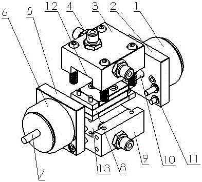
[0033] see figure 1 , Figure 4 , the two-position six-way reversing valve for the pressure-regulating suspended mass sampler consists of electromagnets 1 and 6 mounted on the end covers 2 and 5, a valve cover 3, a valve body 9, positioning blocks 25, 26 and 27, 28 and Ceramic spool 8 composition.

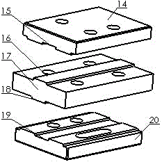
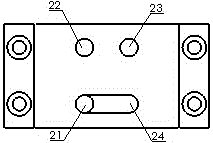
[0034] Such as figure 2 , image 3 , Figure 4 , Figure 5 , Figure 6 As shown, the ceramic valve core 8 is made up of the upper static plate 14, the moving plate 17, and the lower static plate 20. There are water holes 21 and vent holes 22, 23 on the upper static piece 14, and there is a blind groove 24 communicating with the water hole 21 on the contact surface of the upper static piece 14 relative to the moving piece 17; Water holes 33, 36 and air holes 34 have blind grooves 35 communicating with air holes 34 on the contact surface of the lower static plate 20 relative to the moving plate 17; water holes 29, 32 and air holes are arranged on the moving plate 17. 30, 31....


PUM


Abstract

The patent of the present invention provides a reversing valve for a pressure-regulating suspended mass sampler, which has two working positions and six ports. It is composed of valve body, ceramic valve core, stopper, end cover and electromagnet. The ceramic spool is composed of two static pieces and one moving piece. The moving piece and the static piece have water holes, vent holes, blind grooves, shoulders and grooves respectively. The two shoulders on the moving piece are respectively connected to the two static pieces. The valve core is fitted into the seat groove of the valve body and the valve cover. After the valve cover is connected with the valve body by bolts and pressed against the valve core, a hard seal is formed on the contact surface of the moving piece and the static piece. The driving electromagnet pushes the moving piece of the valve core to move left and right through the push rod, so that the water hole and the ventilation hole on the moving piece of the valve core are respectively aligned with the corresponding water hole and ventilation hole on the static piece, and are respectively aligned with the valve body and the valve cover. The water hole and the vent hole are connected to form two independent paths, namely the water path and the air path, to realize the function of path switching. The working reliability and service life of the switching valve can be greatly improved, and the sampling is more accurate.

Description

technical field [0001] The patent of the present invention relates to a two-position six-way reversing valve, which is used for switching the working state of a pressure-regulating suspended mass sampler. Background technique [0002] With the continuous development of the national economy, soil erosion and ecological environment construction have been put on the important agenda. Accurate collection of hydrological and sediment data can provide accurate sediment transport data for the decision-making of water and soil erosion, environmental governance and flood control departments. great practical significance. [0003] The key to collecting hydrological and sediment data is to accurately and timely collect sediment-containing river water samples, which has long been a major problem for hydrological departments. In order to meet the needs of river sediment water sample collection, relevant domestic departments have continuously developed and improved sediment sampling inst...

Claims


Application Information

Patent Timeline
Patent Type & Authority Patents(China)
IPC IPC(8): G01N1/10
Inventor 雷玉勇刘克福张丽蒋代君
Owner XIHUA UNIV
Learn More