
A connector with reduced plugging force and easy plugging

A technology of connectors and plugging force, which is applied in the direction of connection, parts of connecting devices, electrical components, etc., can solve the problems of increasing the size of the connector, reducing the strength and life of the pin, and large plugging force, etc., to achieve Reduce the difficulty of manufacturing and processing, avoid wear or deformation, and make the connection firm and stable

Inactive Publication Date: 2016-03-23
SICHUAN UNIV
View PDF5 Cites 0 Cited by
  • Summary
  • Abstract
  • Description
  • Claims
  • Application Information

AI Technical Summary

Problems solved by technology

[0003] 1. After the miniaturization design, the connector pins and sockets cannot be assembled well, often resulting in poor contact between the pins and the conductors of the socket that is not easy to find, and the strength and life of the pins are greatly improved after miniaturization. decrease;
[0004] 2. The control of the insertion and extraction force. From the perspective of use, the insertion and extraction force should be small to facilitate insertion and extraction. However, if the insertion and extraction force is too small, it will affect the reliability of the contact. After the number of cores in the traditional connector structure increases, it will inevitably It will lead to increased plugging force and inconvenient plugging and unplugging. At the same time, for occasions that require frequent plugging and unplugging of the connector, the life of the connector will inevitably be greatly reduced, and it is easy to cause direct damage to the connector due to improper force;
[0005] 3. In order to effectively prevent the connector from loosening or falling off, and ensure the stable connection between the plug and the socket, a connector locking structure with a suitable structure is also required, but most of the existing ones are bolt-locking connections. The connection is reliable, but the plugging and unplugging The operation process is cumbersome, and the bolt needs to be removed to realize the replacement of the power cord
[0006] Nowadays, there are also some studies on the above problems, but most of them can only solve a single problem or the effect of solving the problem is not good enough
For example, Chinese patent CN103311738A, in view of the problem that the connection structure of the connecting part is not firm, a locking structure is added to the connector, but the locking structure increases the volume of the connector, and the plug part is very long and the cable cannot be bent, which limits the In the occasion of use, and the problem that the relatively large pin is easily damaged due to the insertion and extraction force between the pin and the socket is not solved
Chinese patent CN103311736A, in order to facilitate the unlocking of the connector locking structure, provides a pull-out auxiliary device, but it also does not solve the problems of large insertion force and cumbersome insertion process after the number of pins increases.
[0007] Although the above-mentioned technical solutions have solved the problem to a certain extent, they have not fundamentally solved the problem, which limits the popularization and use of existing small connectors

Method used


Image

  • A connector with reduced plugging force and easy plugging
  • A connector with reduced plugging force and easy plugging
  • A connector with reduced plugging force and easy plugging

Examples


Embodiment Construction

[0025] The present invention will be further described below in conjunction with accompanying drawing, protection scope of the present invention is not limited to the following:

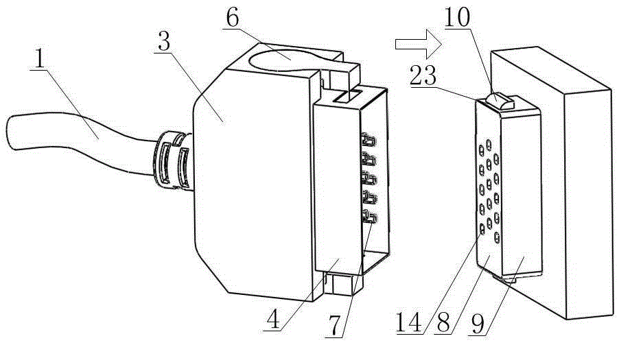
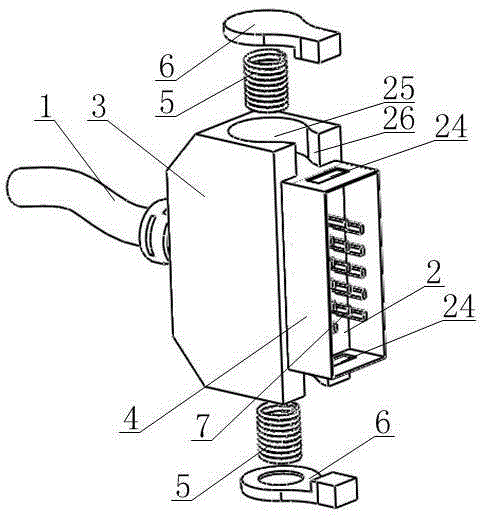
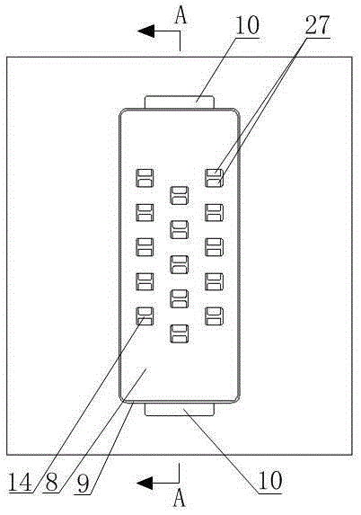
[0026] Such as figure 1 As shown, a connector that reduces the plugging force and is easy to plug and unplug, it includes a plug and a socket, and the direction of movement of the plug relative to the socket during insertion is the mating direction, that is figure 1 In the direction indicated by the arrow, combined with figure 2 As shown, the plug includes a signal line 1, a fixed insulating plate 2, a plastic shell 3, a guide metal shell 4, a button spring 5 and a button 6, and a plurality of pins 7 are installed on the fixed insulating plate 2, and the pins 7 are Flat flakes, the length of the common pin 7, the pin 7 is located at the rear end of the mating direction and connected to the signal line 1, the signal line 1 is the original electronic system, no change, when the plug and the socket ar...


PUM


Abstract

The invention discloses a connector capable of reducing plugging and pulling force and convenient to plug and pull. The connector capable of reducing plugging and pulling force and convenient to plug and pull comprises a plug or a socket. When the plug is plugged into the socket, a guide metal outer shell (4) makes contact with an arc-shaped surface (21) of a lock catch button (10) of the socket, the lock catch button (10) is pressed down by vertically downwards component force of the pressing force, the lock catch button (10) makes contact with a pressing plate (11) through wedge-shaped surfaces, the lock catch button (10) pushes the pressing plate (11) to move forwards in the embedding direction, and then the pressing plate (11) enlarges the interval between two arc-shaped conductive reeds (27). At the moment, plugging pins of the socket does not make contact with the arc-shaped conductive reeds, and when the plugging pins are in place, the lock catch is right ejected out of a locking hole (24) to achieve locking. The connector capable of reducing plugging and pulling force and convenient to plug and pull has the advantages that the plugging and pulling operation is convenient, the plugging and pulling force is small or is not needed in the plugging and pulling process of the plugging pins, and therefore the service life of the connector is largely prolonged. The size of the connector is reduced, more plugging pins can be arranged, and the manufacturing difficulty of the plugging pins and plugging holes is reduced.

Description

technical field [0001] The invention relates to the technical field of connectors, in particular to a connector that reduces plugging force and facilitates plugging. Background technique [0002] The connector is mainly to build a communication bridge between the blocked or isolated circuits in the circuit, so that the current can flow and the circuit can realize the predetermined function. With the rapid development of the electronic technology industry in recent years, connectors are also developing in the direction of miniaturization or miniaturization, and large-core digitalization, which greatly increases the difficulty of electronic connector design and development. The main issues are as follows: [0003] 1. After the miniaturization design, the connector pins and sockets cannot be assembled well, often resulting in poor contact between the pins and the conductors of the socket that is not easy to find, and the strength and life of the pins are greatly improved after...

Claims


Application Information

Patent Timeline
Patent Type & Authority Patents(China)
IPC IPC(8): H01R13/629H01R13/516
Inventor 李文强陈喜李彦王伟王欣于翔麟胡安新
Owner SICHUAN UNIV
Learn More