slurry tank stirring device

A technology of a stirring device and a slurry tank, which is applied to mixer accessories, dissolving, mixers, etc., can solve the problems of increased stirring resistance of the stirring rod, low stirring efficiency, and troublesome operation, and achieves reduced resistance, compact structure, and easy production. Effect

Active Publication Date: 2015-12-30
WUXI CITY CHONGAN DISTRICT TECH ENTREPRENEURSHIP SERVICE CENT
View PDF7 Cites 0 Cited by
  • Summary
  • Abstract
  • Description
  • Claims
  • Application Information

AI Technical Summary

Problems solved by technology

However, after the pulp stays in the pulp tank for a long time, the components in the pulp will partially settle, and it needs to be stirred evenly before being transported to the paper machine. The traditional stirring method is to use a round rod-shaped stirring rod to stir in the pulp tank. After this kind of stirring rod has been used for a period of time, the pulp will hang on the stirring rod, and the stirring resistance of the stirring rod will increase. It must be taken out and cleaned regularly, which is troublesome to operate, and the stirring rod in the shape of a round rod rotates in the pulp At this time, the driving effect on the pulp around the stirring rod is very small, the fluctuation of the pulp is very small, the stirring efficiency is low, the stirring time is long, and the wasted power is much

Method used


Image

  • slurry tank stirring device
  • slurry tank stirring device
  • slurry tank stirring device

Examples


Embodiment Construction

[0014] The present invention will be further explained below in conjunction with the accompanying drawings and specific embodiments. It should be understood that the following specific embodiments are only used to illustrate the present invention but not to limit the scope of the present invention. It should be noted that the words "front", "rear", "left", "right", "upper" and "lower" used in the following description refer to the directions in the drawings, and the words "inner" and "outer ” refer to directions towards or away from the geometric center of a particular part, respectively.

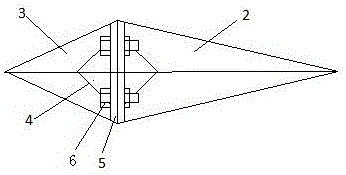
[0015] figure 1 It is a schematic view of the structure of the present invention. As can be seen from the figure, in the present invention, the lower end of the stirring rod 1 is provided with a stirring blade, and the stirring blade includes a front blade 2 and a rear blade 3, and the longitudinal ends of the front blade 2 and the rear blade 3 are provided with a triangular shape. Groove...


PUM


Abstract

The invention discloses a pulp pool stirring blade which comprises a stirring rod with the diamond-shaped cross section. Stirring blade bodies are arranged at the lower end of the stirring rod and comprise front blades and rear blades; triangular grooves are formed in the longitudinal direction of connecting ends of the front blades and the rear blades and are attached to the stirring rod; the longitudinal thickness and the horizontal width of the front blades and the rear blades are respectively reduced from the connecting ends to the outer ends of the front and rear blades; connecting pieces are arranged at the upper and lower ends of the front blades and the rear blades; each connecting piece comprises a middle bending part and flat side edges on two sides; each middle bending part is bent in a V shape; bolt holes are formed in the flat side edges on two sides; the stirring blade bodies are fixed at the lower end of the stirring rod through bolts. The pulp pool stirring blade is simple in structure; one corner of the diamond-shaped stirring rod is aligned to the advancing direction in the process of stirring by the stirring rod in a pulp pool around the circumference, so that the impact area between the stirring rod and paper pulp can be effectively reduced, the resistance of paper pulp on the stirring rod is reduced, and the stirring power consumption is reduced.

Description

technical field [0001] The invention relates to a slurry tank stirring device, which is a stirring blade capable of avoiding slurry hanging and improving stirring efficiency, and belongs to the mechanical field. Background technique [0002] Paper is an indispensable and easy-to-consume disposable product in daily life. The contribution of papermaking to society is irreplaceable. The first stage of papermaking is pulping. Pulping is the preparation of pulp that can be directly transported to the paper machine for papermaking. In the pulping process, the prepared pulp is transported to the pulp chest, and when used, it is directly pumped from the pulp chest to the papermaking process. However, after the pulp stays in the pulp tank for a long time, the components in the pulp will partially settle, and it needs to be stirred evenly before being transported to the paper machine. The traditional stirring method is to use a round rod-shaped stirring rod to stir in the pulp tank. ...

Claims


Application Information

Patent Timeline
Patent Type & Authority Patents(China)
IPC IPC(8): B01F15/00
Inventor 肖运根陈伟新章隆泉过俊宏顾肖红
Owner WUXI CITY CHONGAN DISTRICT TECH ENTREPRENEURSHIP SERVICE CENT
Why Eureka
Try Eureka