Support rod device and substrate bearing device with same

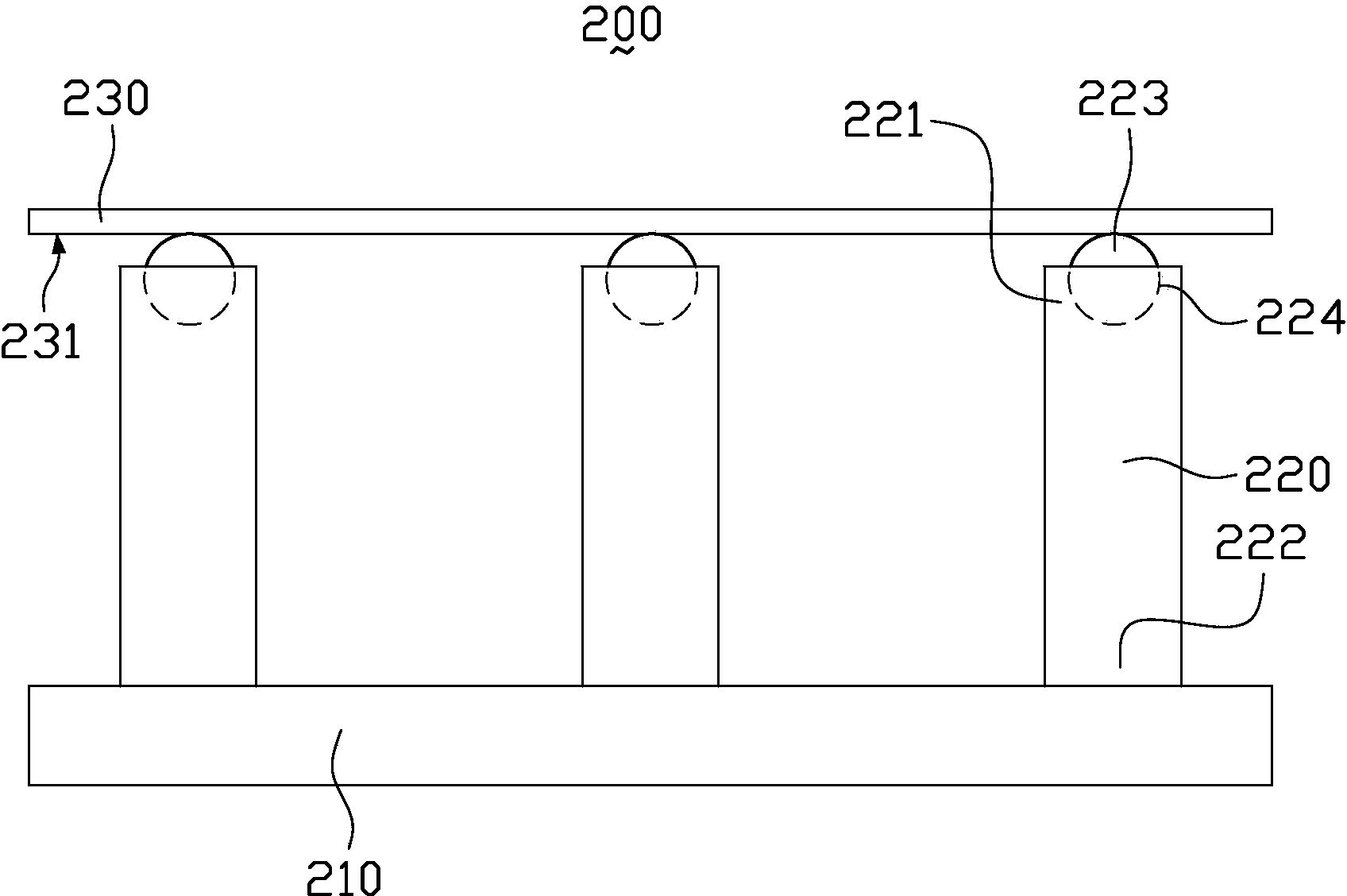
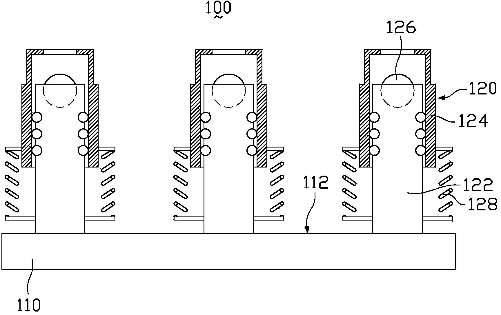
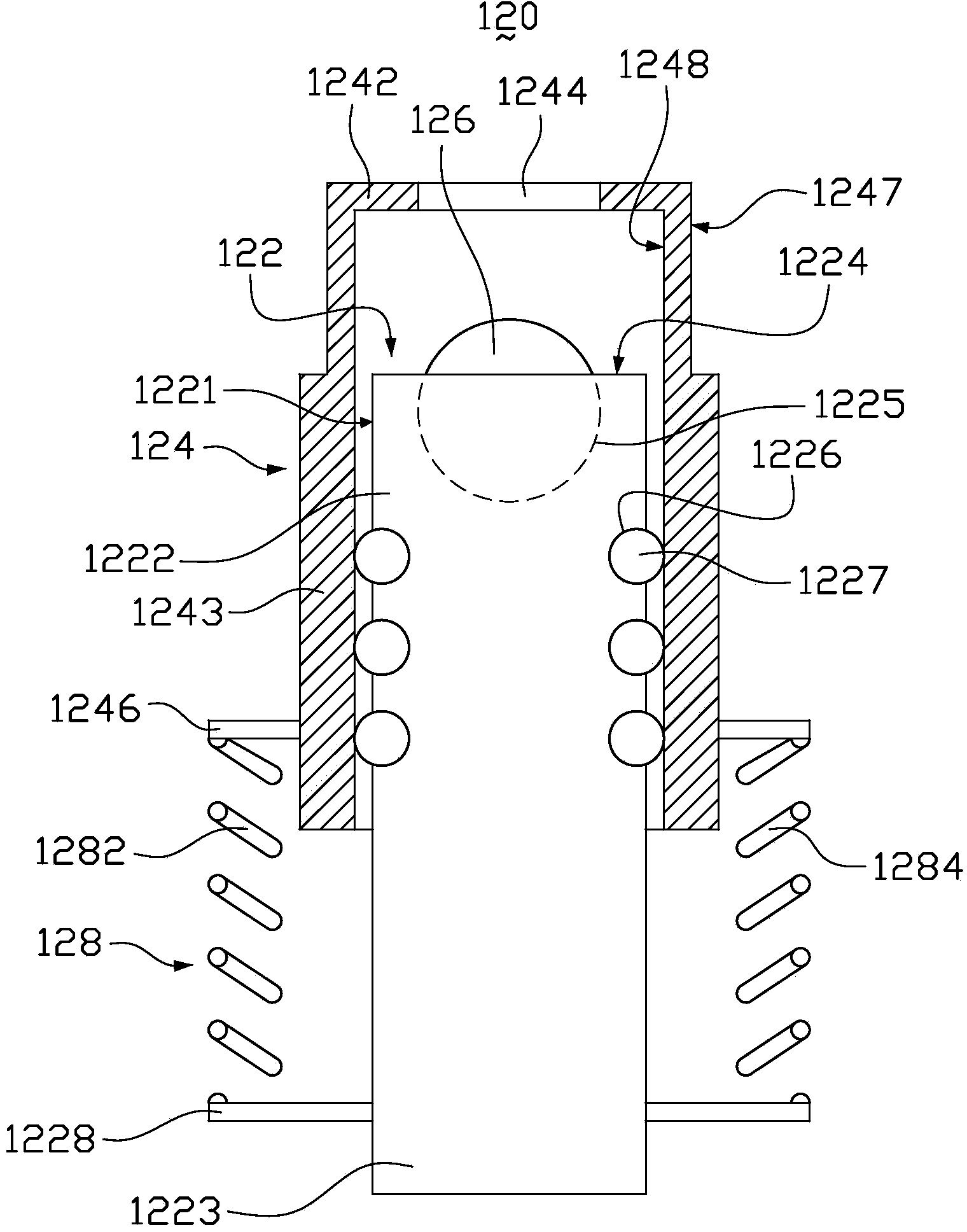
A technology of rod device and support rod, which is applied in the direction of transportation and packaging, conveyor objects, etc., can solve the problems of damage to the substrate 230, small contact area, and concave points at the contact point, etc., so as to prevent damage to the substrate, increase the contact area, increase the The effect of high friction

Active Publication Date: 2014-09-10
KUSN INFOVISION OPTOELECTRONICS
View PDF12 Cites 11 Cited by
  • Summary
  • Abstract
  • Description
  • Claims
  • Application Information

AI Technical Summary

Problems solved by technology

[0004] However, since the lower surface 231 of the substrate 230 is in direct contact with the balls 223 of the struts 220, the weight of the substrate 230 itself and when the external force on the substrate 230 has a vertical component (that is, a component perpendicular to the platform 210) will cause the substrate to Dimples appear at the contact between the lower surface 231 of 230 and the ball 223
The horizontal component of the external force on the substrate 230 parallel to the conveying direction of the substrate 230 makes the substrate 230 still slide relative to the platform 210 along the conveying direction. At this time, the vertical component of the external force subjected to the substrate 230 continues to act on

Method used


Image

  • Support rod device and substrate bearing device with same
  • Support rod device and substrate bearing device with same
  • Support rod device and substrate bearing device with same

Examples


Example Embodiment

[0024] In order to further explain the technical means and effects of the present invention to achieve the intended purpose of the invention, in conjunction with the accompanying drawings and preferred embodiments, the specific implementation of the strut device and the substrate carrying device provided with the strut device according to the present invention will be given below. The method, structure, characteristics and effects are described in detail as follows:

[0025] The foregoing and other technical content, features, and effects of the present invention will be clearly presented in the following detailed description of the preferred embodiment with reference to the drawings. Through the description of the specific embodiments, the technical means and effects of the present invention to achieve the predetermined purpose can be understood more deeply and concretely. However, the accompanying drawings are only for reference and explanation, and are not used to describe the ...


PUM


Abstract

A support rod device comprises a support rod, a support sleeve, support balls, and an elastic element; the support rod comprises a first end and a second end; the first end has a first end face provided with a mounting cell; the support sleeve slidably sleeves the first end of the support rod along the axis of the support rod; the support sleeve is provided with a support portion having a through hole and corresponding to the firs end face; the support ball arranged in the mounting cell of the support rod is partially exposed from the first end face and is aligned with the through hole; the elastic element is connected between the support rod and the support sleeve. The invention further relates a substrate bearing device with the support rod device; by the use of the substrate bearing device, damage of a substrate caused when the substrate is supported by the substrate bearing device can be prevented effectively.

Description

technical field [0001] The invention relates to the technical field of display panel manufacturing equipment, in particular to a strut device and a substrate carrying device having the strut device. Background technique [0002] A Liquid Crystal Display (LCD) is widely used in the field of flat panel display due to its characteristics of low radiation, thin thickness and low power consumption. In the production process of liquid crystal panels, in order to facilitate operation and transmission and avoid damage to the glass substrate, the glass substrate is often placed on a substrate carrying device with a support rod (Pin) to perform the required manufacturing process. [0003] figure 1 It is a structural schematic diagram of an existing substrate carrying device carrying a substrate. Such as figure 1 As shown, the substrate carrying device 200 includes a platform 210 and a plurality of support rods 220 vertically arranged on the platform 210 . The second end 222 of the...

Claims


Application Information

Patent Timeline
IPC IPC(8): B65G47/80
Inventor 朱健
Owner KUSN INFOVISION OPTOELECTRONICS
Why Eureka
Try Eureka