Differential screw height-adjustable LED (light emitting diode) lamp base and T-shaped calibrating form board using same

A technology of LED lamp holder and differential screw, applied in the field of visual measurement, can solve the problems of influence and increase the complexity of calibration, and achieve the effect of convenient use

Active Publication Date: 2014-09-10
HARBIN INST OF TECH
View PDF5 Cites 3 Cited by
  • Summary
  • Abstract
  • Description
  • Claims
  • Application Information

AI Technical Summary

Problems solved by technology

The existing LED plane calibration template needs to be further improved in terms of coplanarity accuracy, portability, and convenience of handheld operation on the calibration site, which affects the accuracy of visual measurement site calibration to a certain extent and increases the complexity of calibration. sex

Method used


Image

  • Differential screw height-adjustable LED (light emitting diode) lamp base and T-shaped calibrating form board using same
  • Differential screw height-adjustable LED (light emitting diode) lamp base and T-shaped calibrating form board using same
  • Differential screw height-adjustable LED (light emitting diode) lamp base and T-shaped calibrating form board using same

Examples


specific Embodiment approach 1

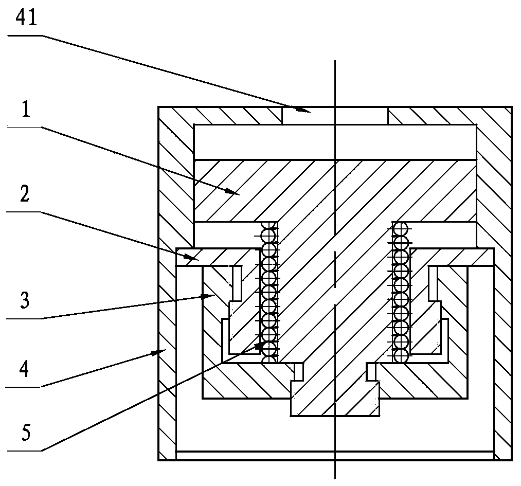
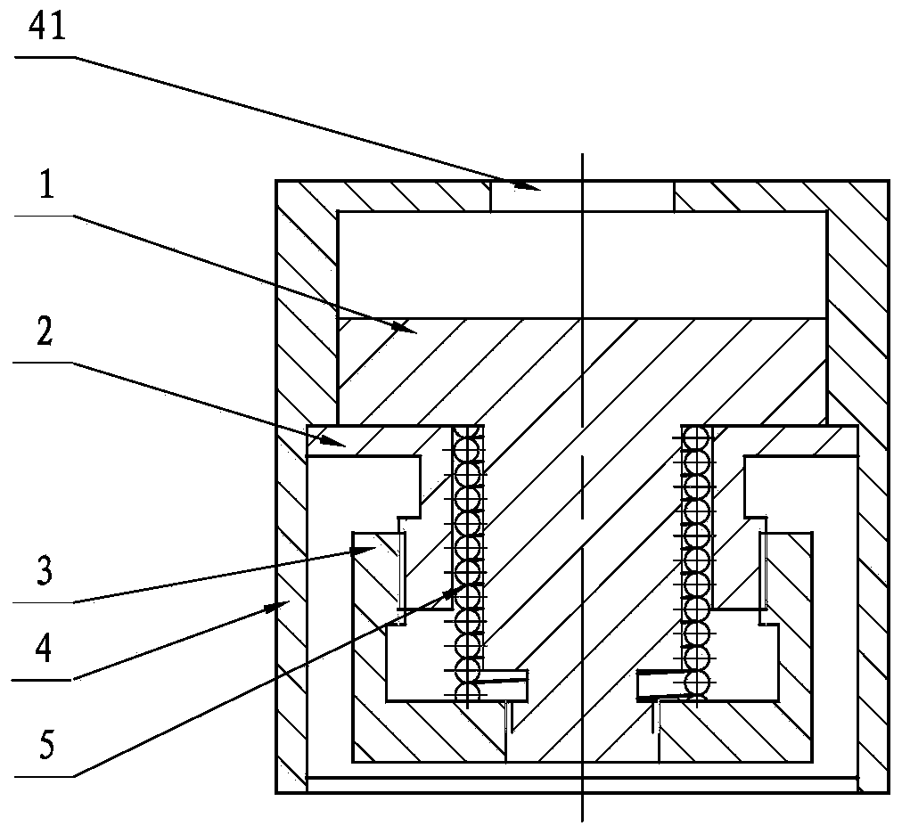
[0009] Specific implementation mode one, see Figure 1-9 This embodiment will be described. This embodiment describes a differential screw height adjustment LED lamp holder, which includes a height adjustment lamp holder 1, a fixing seat 2, an adjustment sleeve 3, a housing 4 and a compression spring 5,

[0010] The housing 4 is a regular hexahedron housing made up of a top surface and four sides. A light-transmitting hole 41 is arranged in the middle of the top surface of the housing 4, and one or more anti-corrosion holes in the vertical direction are provided on the inner wall of the housing 4. transfer chute;

[0011] The height-adjusting lamp holder 1, the fixing seat 2, the adjustment sleeve 3 and the compression spring 5 are all located inside the housing 4, wherein:

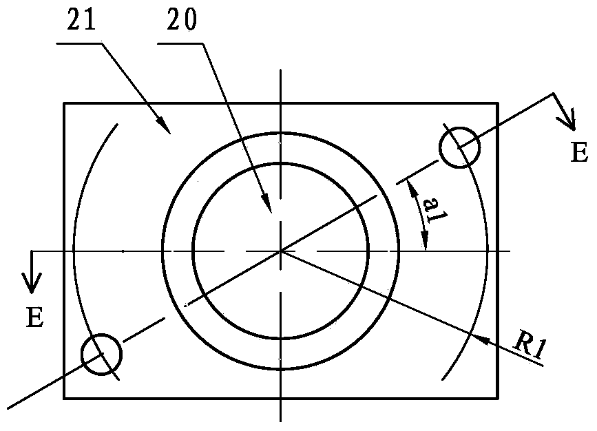
[0012] For the structure of the fixed seat 2, see image 3 and 4 Shown: there is a circular through hole in the middle of the fixed seat 2, the axis of the circular through hole 20 passes through the c...

specific Embodiment approach 2

[0021] Specific Embodiment 2. This embodiment is a further limitation of the differential spiral height-adjusting LED lamp holder described in Embodiment 1. In this embodiment, the outer diameter of the lower part of the height-adjusting lamp holder 1 is outside the d cylinder 12 The external thread of the fixed base 2 is N circles, and the external thread of the base column 22 at the bottom of the fixed seat 2 is also N circles, and the N bit is greater than or equal to an integer of 3.

[0022] In this embodiment, it is defined that the outer diameter of the lower part of the height-adjusting lamp holder 1 is d. The number of turns of the external thread on the outside of the cylinder 12 is equal to the number of turns of the external thread on the base column 22 at the bottom of the fixing seat 2 . The choice of the specific value can be selected according to the height that needs to be adjusted actually, for example: when the height to be adjusted is 3mm, N can be 6.

specific Embodiment approach 3

[0023] Specific Embodiment 3. This embodiment is a further limitation of the differential spiral height adjustment LED lamp holder described in Embodiment 1. In this embodiment, the inner wall of the housing 4 is provided with a shoulder, and the shoulder is used for It is fixedly connected with the rectangular plate-shaped fixed platform 21 on the top of the fixed base 2 .

[0024] The connection method can be realized by bonding, clamping or screw fixing.


PUM


Abstract

The invention provides a differential screw height-adjustable LED (light emitting diode) lamp base and a T-shaped calibrating form board using the same, relates to a vision calibrating form board, and belongs to the technical field of vision measurement. The differential screw height-adjustable LED lamp base consists of a height-adjustable lamp base body, a fixed seat, an adjusting sleeve, a shell and an anti-rotating spring. On the premise that LED spots do not rotate, the LED spots are only adjusted along a vertical direction of a coplane by 0.5mm when the adjusting sleeve rotates at an angle of 360 degrees, and if instruments such as a high-precision coordinate measuring machine and the like are adopted, 5-micrometer coplane adjusting precision of the LED spots can be achieved by manually adjusting the adjusting sleeve. The calibrating form board comprises a planar T-shaped calibrating form board structure consisting of five coplanar infrared LED spots. The differential screw height-adjustable LED lamp base and the T-shaped calibrating form board using the same are suitable for the field of vision measurement on camera parameter calibration by using the form board.

Description

technical field [0001] The invention relates to a visual calibration template, which belongs to the technical field of visual measurement. Background technique [0002] Visual measurement technology is more and more used in the fields of aerospace and civilian products. The equipment used in visual measurement is a camera system, and the camera needs to use a calibration template for on-site calibration of parameters before use. In recent years, the use of LED light spots to form high-brightness calibration templates has become an important research topic in visual calibration technology. The existing LED plane calibration template needs to be further improved in terms of coplanarity accuracy, portability, and convenience of handheld operation on the calibration site, which affects the accuracy of visual measurement site calibration to a certain extent and increases the complexity of calibration. sex. Contents of the invention [0003] The invention provides a height-adj...

Claims


Application Information

Patent Timeline
Patent Type & Authority Applications(China)
IPC IPC(8): F21V21/14G01C25/00F21Y101/02F21Y115/10
Inventor 郭玉波马惠萍梁坤飞陈刚聂飞斌
Owner HARBIN INST OF TECH
Why Eureka
Try Eureka