Combustion chamber based on RQL principle and aircraft engine with same

A combustion chamber and principle technology, applied in the field of aero-engines, can solve problems such as the length of the flame tube is too large, the length and weight of the engine are increased, and the distribution of the outlet temperature field cannot be effectively controlled.

Active Publication Date: 2014-09-10
CHINA AVIATION POWER MACHINE INST
View PDF5 Cites 10 Cited by
  • Summary
  • Abstract
  • Description
  • Claims
  • Application Information

AI Technical Summary

Problems solved by technology

[0005] The purpose of the present invention is to provide a combustor based on the RQL principle and an aeroengine with the combustor to solve the problem that the existing combustor structure still has a relatively large length of the flame tube, which causes the increase of the length and weight of the engine, and the outlet temperature field Technical issues where the distribution cannot be effectively controlled

Method used


Image

  • Combustion chamber based on RQL principle and aircraft engine with same
  • Combustion chamber based on RQL principle and aircraft engine with same

Examples


Embodiment Construction

[0024] The embodiments of the present invention will be described in detail below with reference to the accompanying drawings, but the present invention can be implemented in various ways defined and covered.

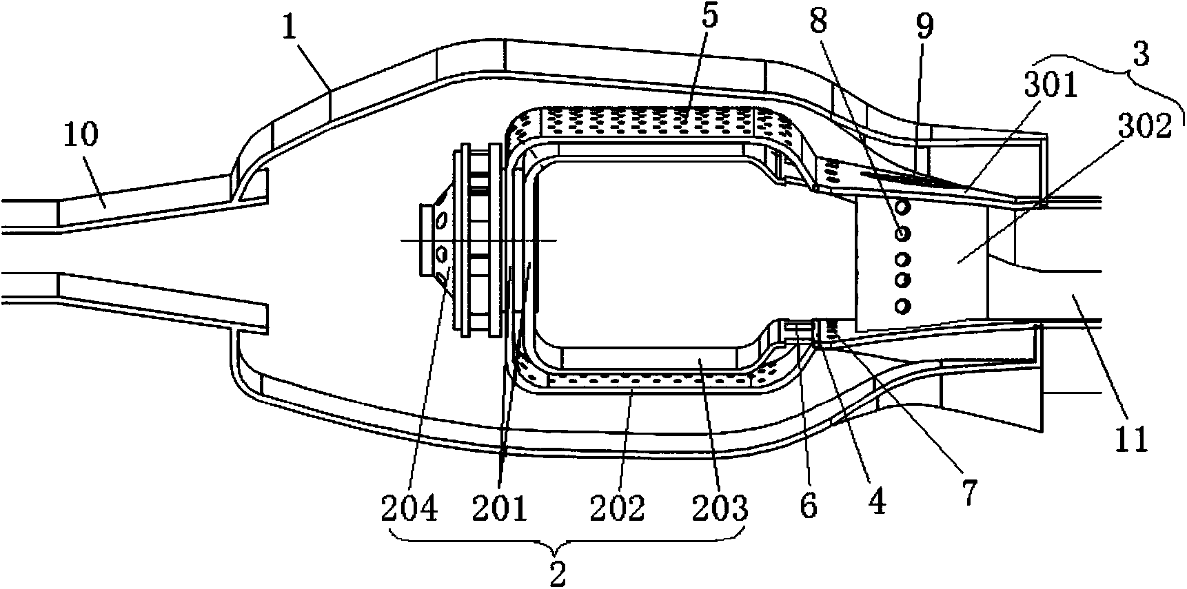
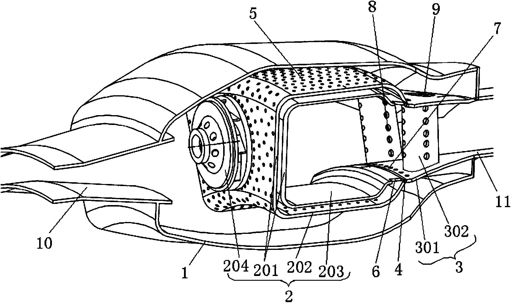
[0025] figure 1 It is one of the structural schematic diagrams of the combustion chamber based on the RQL principle of the preferred embodiment of the present invention; figure 2 It is the second structural diagram of the combustion chamber based on the RQL principle in the preferred embodiment of the present invention.

[0026] like figure 1 and figure 2 As shown, the combustion chamber based on the RQL principle of this embodiment includes a combustion chamber casing 1 and a double-walled flame cylinder 2 disposed in the combustion chamber casing 1, and the inner chamber of the double-walled flame cylinder 2 constitutes an oil-rich combustion chamber. District, the double-walled flame tube 2 includes a flame tube head 201, a flame tube outer wall 202 connected to...


PUM


Abstract

The invention discloses a combustion chamber based on the RQL principle and an aircraft engine with the same. The combustion chamber based on the RQL principle comprises a combustion chamber casing and a double-layer flame cylinder arranged in the combustion chamber casing, the inner cavity of the double-layer flame cylinder forms a fuel rich combustion zone, the double-layer flame cylinder comprises a flame cylinder head, a flame cylinder outer wall, a flame cylinder inner wall and a swirler, and a high-pressure turbine guide vane component forming a quenching mixing zone and lean combustion zones is arranged between the double-layer flame cylinder and the combustion chamber casing; the double-layer flame cylinder and the high-pressure turbine guide vane component are connected integrally, and the high-pressure turbine guide vane component and the combustion chamber casing are connected integrally; the quenching mixing zone is arranged at the connection of the high-pressure turbine guide vane component and double-layer flame cylinder; the high-pressure turbine guide vane component comprises high-pressure turbine guide vanes, guide vane passages are formed between adjacent high-pressure turbine guide vanes, and the lean combustion zones are formed in the guide vane passages. The high-pressure turbine guide vane component is prevented from ablation through cold gas flowing through the guide vanes.

Description

technical field [0001] The invention relates to the field of aero-engines, in particular to a combustion chamber based on the RQL principle. In addition, the present invention also relates to an aeroengine comprising the above-mentioned combustion chamber based on the RQL principle. Background technique [0002] The main development direction of aero-engine combustor technology is low pollution and economy. In addition to meeting the increasingly stringent aero-engine pollution emission standards (the current CAEP6 standard), the aero-engine combustor must also meet economic requirements, namely lighter weight and lower fuel consumption. Often these two requirements conflict with each other, often at the expense of the structural simplicity of the combustion chamber in order to achieve the goal of low pollution emissions. Most low-pollution combustors, such as axial and radial staged combustors, LPP (Lean Premixed Prevaporized) combustors, and LDI (Lean Direct Injection) c...

Claims


Application Information

Patent Timeline
Patent Type & Authority Applications(China)
IPC IPC(8): F23R3/42
Inventor 江立军严明超王利宋双文曹俊
Owner CHINA AVIATION POWER MACHINE INST
Why Eureka
Try Eureka