Amputees who use a
lower limb prosthesis equipped with a
knee joint, find certain movements difficult to perform.
For example, the fact that the prosthesis comprises a mechanical apparatus performing the duty of the joint that is substantially distal to the hip can induce a lack of balance.
Indeed the pressures can become unbearably high-often resulting in an occurrence of friction burns arising through
sliding contact with the prosthesis stump.
Naturally there is a transition across length, but practice bears out that a “heavy” prosthesis is beneficial to the long-femured transfemoral amputee for reasons of body
mass symmetry, and very cumbersome and uncomfortable for the short-femured transfemoral amputee, a distinct sub-class of transfemoral amputee the disclosure is made.
A fourth type of prosthesis is exemplified by a number of relatively expensive, external battery powered, electromechanical knee joints having sensors and dampers operating under
software control for control of the same joint function, albeit with a relatively high
mass (approx.
In the case of a stumble the
knee joint will bend further and collapse, being a most undesirable outcome.
Indeed, neither such a mechanism, nor the polycentric mechanism allow any change in bending resistance once the load is on the
forefoot /
toe.
Accordingly, a stumble will certainly lead to a collapse.
It will be realized that during normal swing function, a stance resistance would be most undesirable.
It will be appreciated that the short stumped, above knee amputee is not well served by these devices of the prior art, especially those that use a default stance mechanism wherein bodyweight on the
forefoot at
toe-off is required to release the knee into a swing mode.
For example, the need for specific stump movement to drive the prosthesis into swing under a residual toe-load can be too much.
While one important issue is the effective weight arising from gravity, a more troublesome issue arises upon use and, in particular, upon a forward swing of the prosthesis.
Known
prosthetic knee joints that are activated only by the application of weight cannot substantially assist the short stumped individual.
The weight placed on the toe, as in toe-off, will typically cause disengagement of any stance mode there otherwise might be.
In summary, known
prosthetic knee & limb devices are either light weight—a benefit, with meager function or safety—a significant
disadvantage, but if the
engineering requirements are met—a benefit, the
inertial mass of the device is too high for comfort—a significant
disadvantage, liable to cause unwanted side effects such as the occurrence of friction burns on the distal stump.
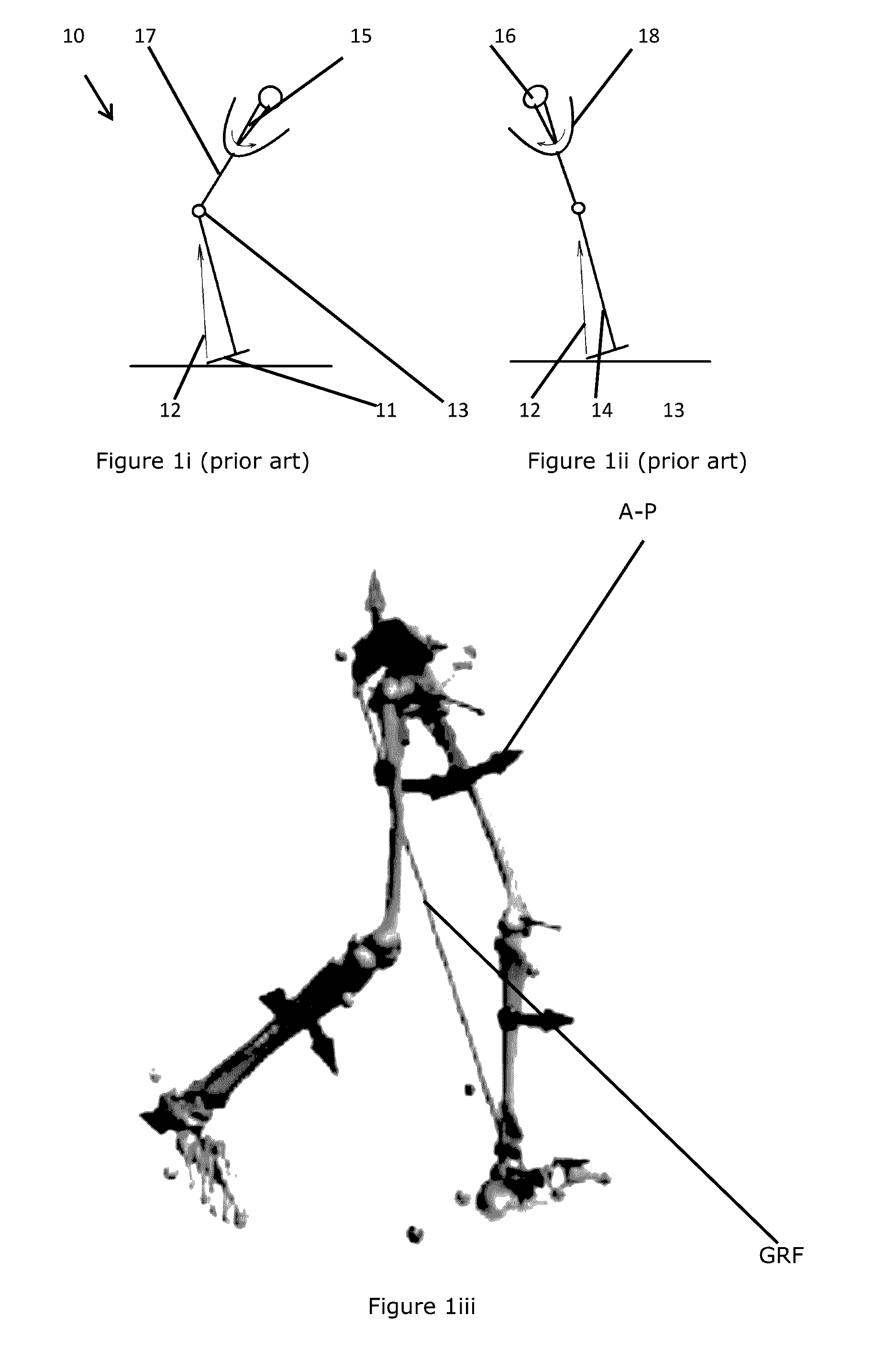
When the artificial limb apparatus allows commencement of partial collapse, the
ground reaction force would start to tilt forward in reaction to a
thigh extension
reflex, and in accordance to Yuichi's teaching the knee would stabilize and due to the
body weight sliding backwards relative to the knee axis, the hydraulic resistance would soon increase to its maximum, but not be under useful voluntary control.
When walking down a stair, the
thigh is at approximate 15° relative to vertical, which means that in the
time frame of single leg
weight bearing, the “AP” force component delivered to the control device is only 25% (sin 15°) of the
body weight, meaning that the resistive torque that slows down the descent of the body will permit a g-force of 75%×9.81 to act on the body, which would result in an uncontrolled descent.
This means that the forward swinging
thigh must provide a sudden rearward kick in mid-swing to provide that resistance to mid-swing flexion control, which is naturally not possible, or likely to provide an ungainly spectacle.
However, for individuals with a short transfemoral stump, the precise control with respect to the resilient element is difficult at best, taking into account the characteristics that if the device can be set such that the required force to control is the same as the force returned by the controller, and that individuals with short transfemoral stumps often have limited strength in their leg stump to control a distal device.
The body is naturally stable if the GRF passes anterior to the knee center, but the “AP”
force vector from the GRF, is oppositely directed with respect to the hip's “AP”
force vector and in this
scenario the “AP”
force vector as per Yuichi would force the knee into stability, which would be undesirable.
This would result in an immediate knee collapse, followed by a rapid transition to a posterior direction of the “AP” force by the hip and the knee would find stability again and a fall would be arrested, but all at a cost of unstable performance.
As would be apparent to a skilled man, this would cause the teaching of certain prior art systems (e.g. Yuichi) teaching to create a free knee joint, which is contrary to the desired response.
It is believed that isolation of a single force “AP” component has not been shown to be sufficient for the control of a prosthesis.
While the sensor is proximal to the knee center, the actual controlling apparatus is distal to the knee center, which is a general conceptual drawback as indicated in the state of the art.
Further, the specification of Blatchford provides a clear limitation of
operability between 0-35° (GB page 2, ¶.22-25), which is believed to arise, at least in part, from the nature of the reaction forces in hydraulic systems and the limitations placed on linear transducers: when the knee bends under resistance over a certain angle; not only does the mechanical leverage over the knee increase with progressive knee angle increasing
signal strength in Blatchford's sensor, but also the shortening lever arm for operating
piston with increasing
knee flexion requires an ever higher
hydraulic pressure inside to produce resistive
bending moment to the knee.
In a specific example, in the event that a strong force is generated by a forward swing,
inertia arising from a distal element will increase the
mechanical force sensed by the sensor, and result in an over-estimate of the level of damping required, which would then reduce its resistance to balance the
system response, making the response of the prosthesis too weak.
Certainly, using a
system in accordance with such teaching, with a sensor positioned adjacent the knee (to minimize the above mentioned disadvantages in relation to stump generated forces affecting the sensor signals that are likely to register knee bending moments), will not allow efficient
operability of the hydraulic
actuator if sensor is placed remote from the knee center.
However, such an approach to placement of a sensor in an appears to be at
odds with the other ramifications of the specific teaching mentioned in this document.

