Method for testing property of high-accuracy fiber-optic gyro on basis of dynamic condition of incremental method

A fiber optic gyroscope and dynamic condition technology, which is applied to measuring devices and instruments, can solve the problems of lack of testing and calibration methods for high-precision fiber optic gyroscope dynamic micro-errors, and achieve high precision, simple operation, and accurate and reliable conclusions

Inactive Publication Date: 2014-09-10
HARBIN ENG UNIV
View PDF6 Cites 16 Cited by
  • Summary
  • Abstract
  • Description
  • Claims
  • Application Information

AI Technical Summary

Problems solved by technology

[0004] According to the relevant literature published at home and abroad, there is currently a lack of an i

Method used


Image

  • Method for testing property of high-accuracy fiber-optic gyro on basis of dynamic condition of incremental method
  • Method for testing property of high-accuracy fiber-optic gyro on basis of dynamic condition of incremental method
  • Method for testing property of high-accuracy fiber-optic gyro on basis of dynamic condition of incremental method

Examples


Embodiment Construction

[0024] The present invention is described in more detail below in conjunction with accompanying drawing example:

[0025] combine Figure 1~2 , the technical solution adopted by the present invention to solve its technical problems is:

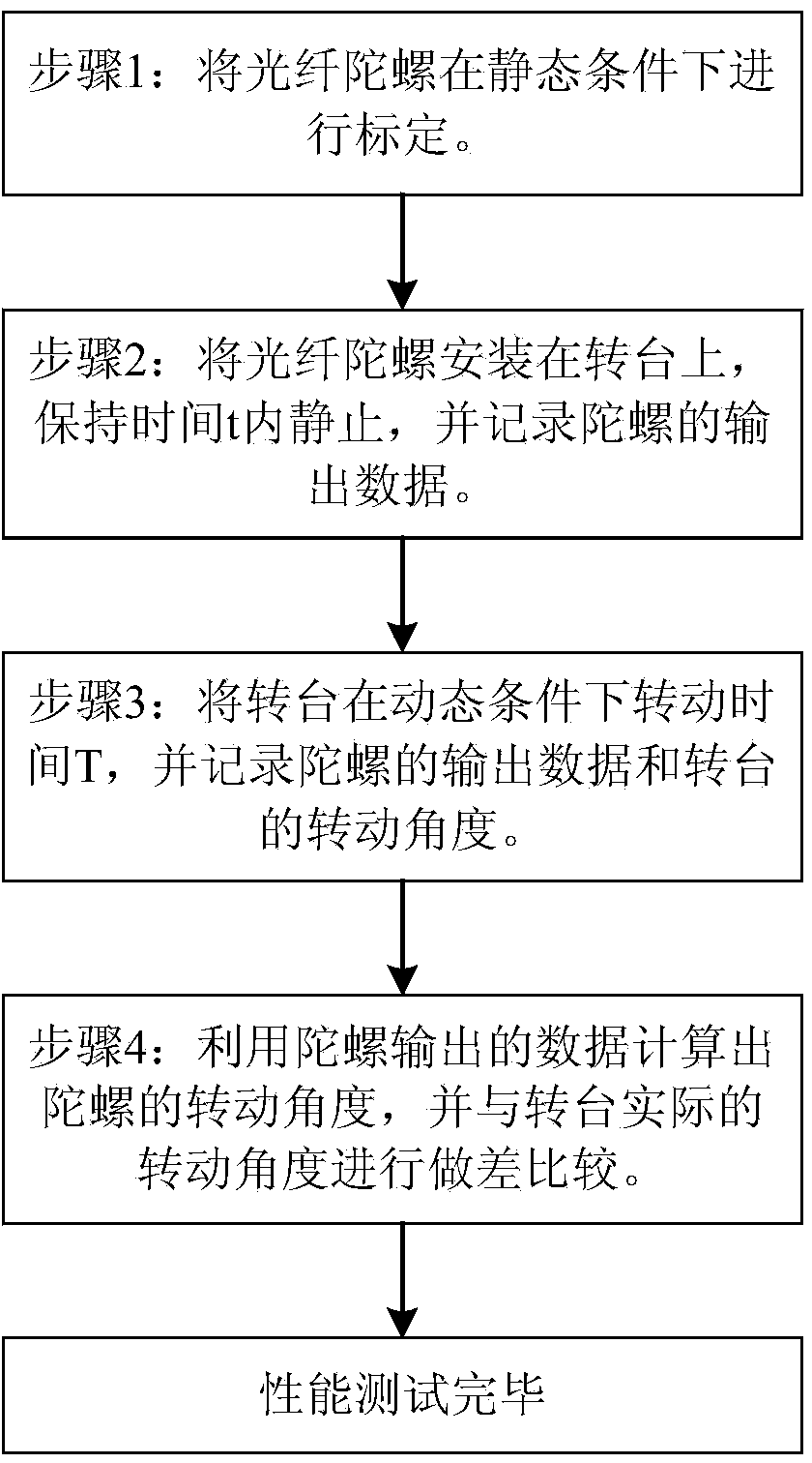
[0026] (1) Calibrate the fiber optic gyroscope to be tested under static conditions, and determine the scale factor, installation error angle, and zero correction value of the fiber optic gyroscope.

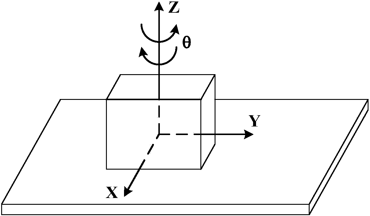
[0027] (2) Install the calibrated optical fiber gyroscope to be tested on the turntable and turn it to the sky, so that the sensitive axis of the optical fiber gyroscope is perpendicular to the horizontal plane. After a static time t, use the data receiving software to record the output angular velocity N of the optical fiber gyroscope within the time t. e , and calculate the average value S of the fiber optic gyro output during this period, which is used to test the average output value of the gyro caused by the rotation of the earth.

[0028]...


PUM


Abstract

The invention aims at providing a method for testing the property of a high-accuracy fiber-optic gyro on the basis of the dynamic condition of an incremental method. The method comprises the following steps of calibrating the fiber-optic gyro under a static condition, and determining a scale factor, an installation error angle and a zero correction value; installing the fiber-optic gyro on a rotating table, rotating the fiber-optic gyro towards the sky so as to enable the Z shaft of the fiber-optic gyro to be perpendicular to a horizontal surface, recording the output angular speed Ne of the fiber-optic gyro within time t, and calculating the output average value of the fiber-optic gyro; controlling the rotation time T of the rotating table, recording N discrete gyro output values output from the Z shaft of the fiber-optic gyro under the condition of a sampling time interval dt, and recording the rotation angle of the rotating table within time T; determining the rotation angle of the fiber-optic gyro within the time T by adding the N fiber-optic gyro output values and subtracting angular speed caused by the autorotation of the earth within the time, and comparing the rotation angle of the fiber-optic gyro with the rotation angle of the rotating table. The method provided by the invention can effectively reflect the light error of the high-accuracy fiber-optic gyro under the dynamic condition.

Description

technical field [0001] The invention relates to a measuring method, in particular to a fiber optic gyroscope testing method. Background technique [0002] The fiber optic gyroscope is a new type of all-solid-state fiber optic sensor sensitive to angular rate and angular deviation based on the Sagnac effect. Because it has the advantages of impact resistance, anti-acceleration motion, high sensitivity, long life, wide dynamic range, small size, light weight, and low price. In recent years, it has been widely promoted and applied to mobile carriers such as aircraft and ships, and has broad development prospects and application prospects. [0003] How to improve the accuracy of high-precision fiber optic gyroscopes has always been an important issue that researchers have paid more attention to. However, the calibration of traditional fiber optic gyroscopes is performed on a precision turntable. The calibration methods include static multi-position experiments and angular rate ...

Claims


Application Information

Patent Timeline
IPC IPC(8): G01C25/00
CPCG01C25/00
Inventor 李绪友孙波于莹莹王岁儿凌卫伟郭丽姝刘攀张志永郭慧许振龙
Owner HARBIN ENG UNIV
Why Eureka
Try Eureka