

Shaft-type part multi-arc chamfer designing method
A technology of shaft parts and design method, applied in the field of multi-arc chamfering design of shaft parts
- Summary
- Abstract
- Description
- Claims
- Application Information
AI Technical Summary
Problems solved by technology
Method used
Image

Examples
Embodiment Construction
[0026] The present invention will be further described below in conjunction with drawings and embodiments.
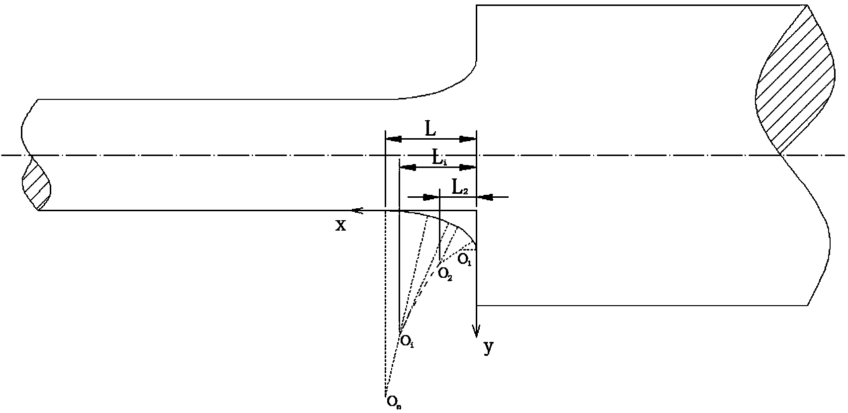
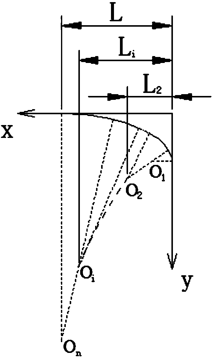
[0027] Please refer to figure 1 and figure 2 As shown, the multi-arc chamfering design method for shaft parts of the present invention comprises the following steps:
[0028] Step 1). Provide shaft parts, use 3D drawing software to carry out 3D CAD modeling of the shaft parts, the shaft parts include the small diameter section on the left and the large diameter section on the right, where the small diameter section and the large diameter section The joint of the shaft is the step;
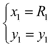
[0029] Step 2). Carry out multi-arc parametric modeling at the two vertical sides at the axial step of the small diameter section and the large diameter section. There are n sections of arcs, and the radius of the arcs is from R 1 to R n gradually becomes larger, the smallest arc R 1 and the large diameter segment side of shaft parts ( figure 2 tangent to the middle vertical side y-a...
PUM
 Abstract
Description
Claims
Application Information