Spare power automatic switching emergency device and method for power system of transformer substation

It is a technology of station power consumption and backup and self-switching. It is applied to circuit devices, emergency power supply arrangements, electrical components, etc. It can solve the problems of busbar voltage loss, complex product types, and unfavorable maintenance in the station power system, and achieve zero-sequence protection. , to avoid long-term pressure loss, the effect of simple and convenient installation

Active Publication Date: 2014-09-10
SHENZHEN POWER SUPPLY BUREAU
View PDF2 Cites 3 Cited by
  • Summary
  • Abstract
  • Description
  • Claims
  • Application Information

AI Technical Summary

Problems solved by technology

[0003] At present, the self-switching devices of substation station power system are widely used in various substations of the power system. The device involves too many manufacturers and the product types are too complicated. The disadvantages are: 1. Due to too many manufacturers, once If the device fails, it needs to be returned to different manufacturers for replacement, which wastes a lot of time. In particular, some types of devices have been discontinued, and the waiting time for upgrading is too long, which increases the risk of busbar voltage loss in the station power system; 2. The product type is too complicated. It is not conducive to maintenance, and at the same time, in order to ensure that device failures can be quickly resolved, it is necessary to reserve a large number of spare devices of various product types, thus wasting a lot of financial resources

Method used


Image

  • Spare power automatic switching emergency device and method for power system of transformer substation
  • Spare power automatic switching emergency device and method for power system of transformer substation
  • Spare power automatic switching emergency device and method for power system of transformer substation

Examples


Embodiment Construction

[0042] In order to make the object, technical solution and advantages of the present invention clearer, the present invention will be further described in detail below in conjunction with the accompanying drawings.

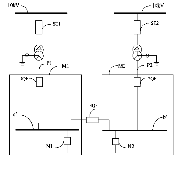
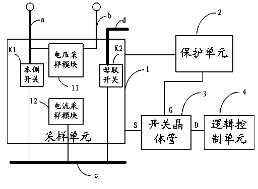
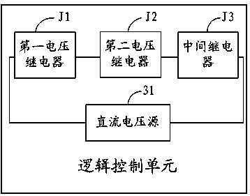
[0043] Such as figure 2 As shown, the embodiment of the present invention provides a self-switching emergency device for the power system of a substation station, which is installed in the incoming line panel of any substation station to realize the switching between the power supply for the station on the local side and the power supply for the station on the opposite side , for the sake of simplicity, the following is an example of the self-switching emergency device installed in the station power system of the local station. In the embodiment of the present invention, the substation station power system is equipped with an emergency device for automatic switching, the device includes a sampling unit 1, a protection unit 2, a switching transistor 3 and a logic ...


PUM


Abstract

The invention provides a spare power automatic switching emergency device for a power system of a transformer substation. The spare power automatic switching emergency device comprises a sampling unit, a protection unit, a switching transistor and a logical control unit, wherein an own side switch in the sampling unit is connected with an own side power supply incoming line and a bus, a bus coupler switch is connected with own and opposite side buses, a voltage sampling module is connected with own and opposite side power supply incoming lines, and a current sampling module is connected with an own side bus; the protection unit is connected with the sampling unit, and is used for determining a working mode and transmitting a level signal to the switching transistor according to the current value of the own side bus; the switching transitor is connected with the three units respectively, and is switched on or off according to the magnitude of the level signal; the logical control unit is used for determining to start up the own side power supply incoming line or the opposite side bus to supply power to the own side bus according to the three-phase voltage values of the own and opposite side power supply incoming lines when the switching transistor is switched on. The spare power automatic switching emergency device is simple in structure and is convenient to detach, the risk of long-time voltage loss of the own side bus is avoided, and a large quantity of financial resources and time are saved.

Description

technical field [0001] The invention relates to the technical field of power system substation power consumption systems in electric power systems, and in particular to a device and method for automatic switch-on emergency of substation power system power consumption systems. Background technique [0002] Such as figure 1 As shown, the substation station power system provides a stable and reliable 380V AC power supply for the AC loads in the substation. Its common configuration is that the I-section bus a' and the II-section bus b' operate separately, and the I-section bus a' and the II bus b 'The AC power is respectively drawn from the low-voltage side of two station transformers that are mutually standby, that is, the I-section busbar a' is transformed from a 10KV AC power supply to #1 station through the variable height switch ST1 of the station transformer and other transformer devices The incoming line of station #1 of power supply P1 supplies power, and the busbar b' ...

Claims


Application Information

Patent Timeline
Patent Type & Authority Applications(China)
IPC IPC(8): H02J9/06
Inventor 周永光佘楚云曹建伟林文校
Owner SHENZHEN POWER SUPPLY BUREAU
Why Eureka
Try Eureka