
Multi-station punching machine

A multi-station, punching technology, applied in the field of stamping press machines, can solve the problems of worker injury, hidden dangers, fast stamping action, etc., and achieve the effect of reducing labor intensity, safe operation and use, and improving processing efficiency.

Inactive Publication Date: 2014-09-17
李良有
View PDF0 Cites 3 Cited by
  • Summary
  • Abstract
  • Description
  • Claims
  • Application Information

AI Technical Summary

Problems solved by technology

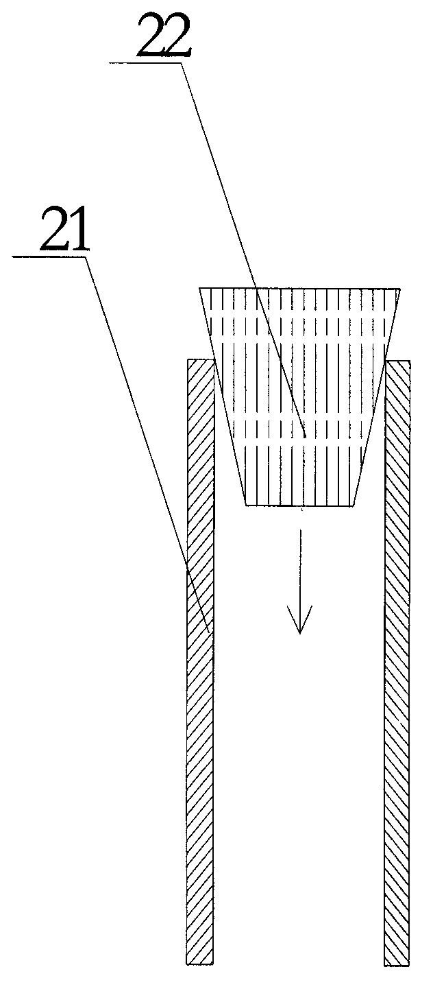
[0013] First of all, the above-mentioned process can still only process one end of the metal tube 21 during the processing process, and cannot realize the technical requirements of processing the upper and lower ends of the metal tube 21 at the same time;
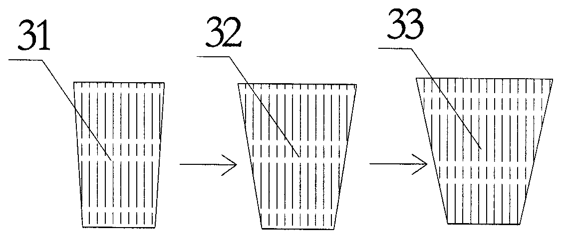
[0014] Secondly, whether it is to use multiple punches for stamping or to replace the punch on the same punch, it is necessary to install and adjust the position of the metal tube or install and adjust the position of the punch during the processing. It is easy to imagine that in During the above-mentioned multiple installation and adjustment processes, it is easy to cause a positional deviation between the center point of the punch and the horizontal center point of the metal pipe, resulting in a lack of precision and affecting the processing accuracy and quality of the finished component
[0015] Third, due to the high punching force and fast punching action of the punching machine, workers may be injured due to misoperation during the above-mentioned operations of repeatedly removing and placing metal pipes, which poses certain safety hazards;
[0017] In addition, it should be pointed out that because the punch of the punch presses downward, the pressure is relatively high, so that the lower part of the metal tube installed on the punch press is closely attached to the part in contact with the punch press, and the upper part of the metal tube is closely attached to the punch. This has caused the technical defect that the lower part of the metal tube is not easy to be taken out from the punch or the upper part is brought up by the punch that resets upwards.

Method used


Image

  • Multi-station punching machine
  • Multi-station punching machine
  • Multi-station punching machine

Examples


Embodiment Construction

[0037] Such as Figure 4-5As shown, a multi-station punch press includes a punch main body 4, a die device 5, a stamping power unit 6 and a control device 7 are arranged on the punch main body 4, and at least two Guide post 41, the guide post 41 is vertically arranged and evenly distributed relative to the horizontal plane, the power output end of the stamping power device 6 is connected to the die device 5, and the die device 5 is sleeved and slidably installed on the guide On the column 41 and under the drive of the stamping power device 6, it reciprocates longitudinally on the guide column 41 perpendicular to the horizontal plane. The die device 5 is provided with two or more than two punches 51, and the punches 51 Arranged in sequence according to the slope of the punching head, the punch body 4 is also provided with a lower die 42, the lower die 42 is horizontally arranged and opposite to the die device 5, and the workpiece to be processed is vertically arranged relative ...


PUM


Abstract

The invention provides a multi-station punching machine. The multi-station punching machine comprises a punching machine main body, wherein the punching machine main body is provided with a die stamping device, a stamping power device and a control device; the punching machine main body is also provided with at least two guide posts; the guide posts are perpendicularly arranged relative to the horizontal plane and are uniformly distributed; the power output end of the stamping power device is connected with the die stamping device; the die stamping device sleeves the guide posts in a sliding manner and is driven by the stamping power device to longitudinally reciprocate on the guide posts in a direction perpendicular to the horizontal plane; the die stamping device is provided with two or more punches; the punches are sequentially arranged according to stamping surface slopes of the punches; the punching machine main body is also provided with a lower die; the lower die is horizontally arranged and is opposite to the die stamping device; a workpiece to be machined is arranged in the lower die vertical to the horizontal plane.

Description

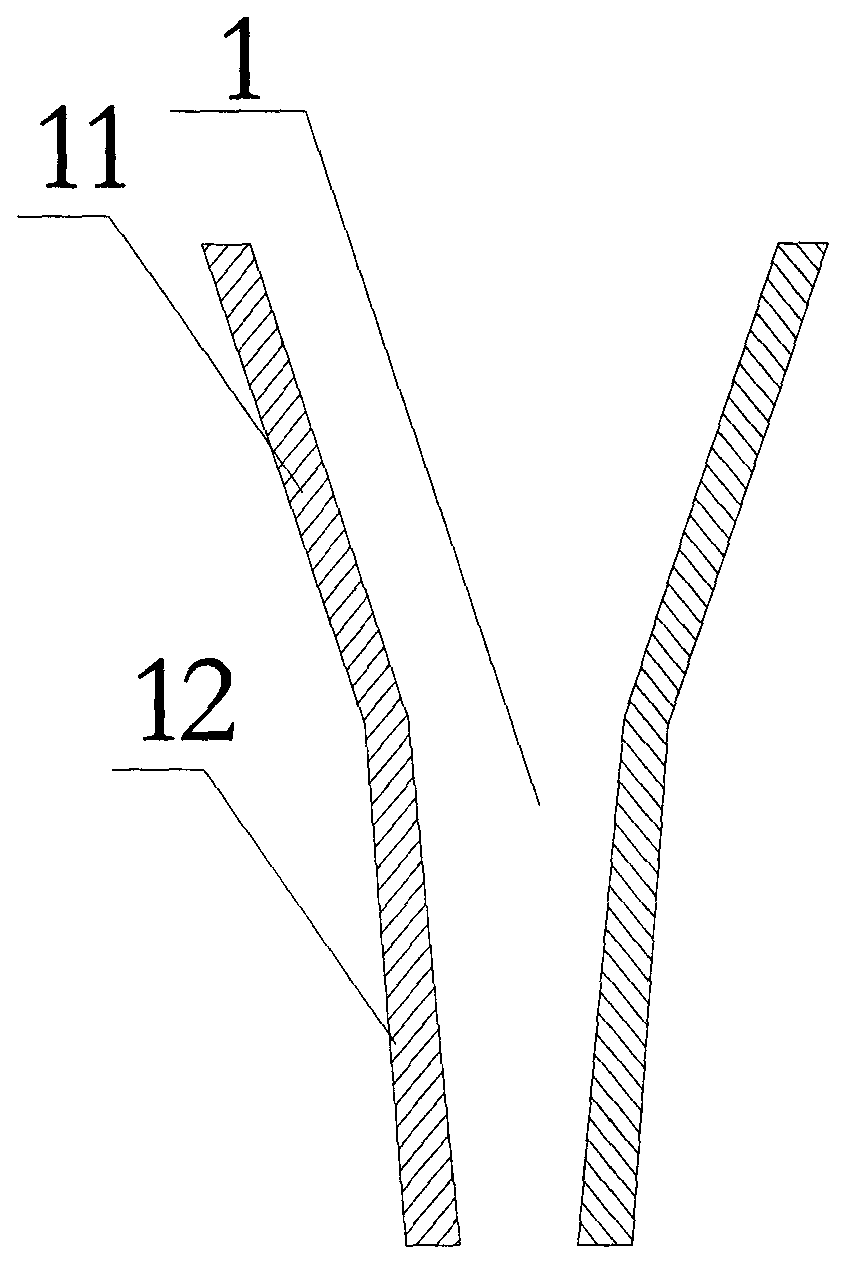
【Technical field】 [0001] The invention relates to a stamping press machine, in particular to a multi-station punching machine. 【Background technique】 [0002] The punch press is a stamping press. In industrial production, the stamping process has the advantages of saving materials and energy compared with traditional mechanical processing, high efficiency, low technical requirements for operators, and through various mold applications, it can make products that cannot be achieved by mechanical processing. , so it is more and more widely used. [0003] However, with the rapid development of the processing and manufacturing industry, the defects and deficiencies of existing punching machines in the processing of special-shaped parts have also attracted people's attention. The following examples are given to illustrate: [0004] Such as figure 1 as shown, figure 1 It is an existing tubular special-shaped member 1 usually used in air-conditioning connecting pipes. The tubula...

Claims


Application Information

Patent Timeline
Patent Type & Authority Applications(China)
IPC IPC(8): B21D22/02B21D19/00
Inventor 李良有
Owner 李良有
Learn More