Eureka AIR delivers breakthrough ideas for toughest innovation challenges, trusted by R&D personnel around the world.

Right mounting bracket blanking and punching composite die

A technology of blanking, punching and composite molds, which is applied in the field of mechanical processing, can solve the problems of easy out-of-tolerance processing dimensions, high labor intensity, and high production costs, and achieve the effects of good dimensional consistency, low labor intensity, and easy operation

Inactive Publication Date: 2014-09-17
HENGYANG FENGSHUN AXLE CO LTD
View PDF0 Cites 7 Cited by
  • Summary
  • Abstract
  • Description
  • Claims
  • Application Information

AI Technical Summary

Problems solved by technology

[0002] The right mounting bracket is the main accessory of the front axle assembly on the chassis of the car. There is a conduit welded on the mounting bracket. The conduit is used to install the rubber bushing and play a buffer role. Therefore, the technical requirements are relatively high. At present, the right mounting bracket It is formed by tailor welding, and then drilled, that is, the two processed plates are assembled and welded first, and processed on a drilling machine. This processing method is inefficient, labor-intensive, and the processing size is easy to exceed tolerance. The products can not meet customer requirements, and the production cost is too high

Method used


Image

  • Right mounting bracket blanking and punching composite die
  • Right mounting bracket blanking and punching composite die
  • Right mounting bracket blanking and punching composite die

Examples


Embodiment Construction

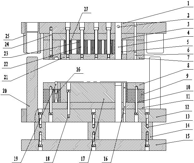
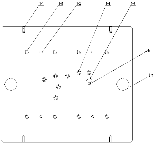
[0034] As shown in the accompanying drawings: a blanking and punching compound die for the right mounting bracket, which includes: an upper die assembly and a lower die assembly.

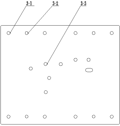
[0035] Described patrix assembly comprises patrix 1, fixed pin 2, patrix backing plate 3, square punch 4, rubber 5, the 1st cylindrical pin 6, die piece piece 7, unloading plate 21, unloading screw 22 , unloading rubber 23, hexagon socket head cap screw 24, guide sleeve 25, small round rubber 27; the upper mold base 1 is located at the top of the mold, the upper mold backing plate 3 is located under the upper mold base 1, and the die block 7 is located on the upper Below the die backing plate 3, the die block 7, the upper die backing plate 3, the upper die seat 1 are connected together by the hexagon socket head cap screw 24 and the 1st cylindrical pin 6, the discharge plate 21, the rubber 5, the discharge rubber 23. The small round rubber 27 is located in the blanking hole in the middle of the die ...


PUM


Abstract

The invention provides a right mounting bracket blanking and punching composite die. The right mounting bracket blanking and punching composite die comprises an upper die assembly and a lower die assembly. The upper die assembly comprises an upper die base, a fixing pin, an upper die base plate, a square male die, rubber, a female die splicing block, a stripper plate, stripper screws, stripping rubber, guide sleeves and small round rubber. The upper die base is located on the uppermost portion of the die. The upper die base plate is located below the upper die base. The female die splicing block is located below the upper die base plate. The square male die is located in the upper die base. The fixing pin is located in the square male die. The lower die assembly comprises ejector plates, ejection rubber, a lower die base plate, a lower die base, cushion blocks, a base plate, a male die splicing block, locating pins, guide posts and small cylindrical springs. The base plate is located on the lowermost portion of the die. The cushion blocks are located above the base plate. The lower die base is located above the cushion blocks. The lower die base plate is located above the lower die base. The male die splicing block is located above the lower die base plate. The ejector plates are located beside the male die splicing block. According to the right mounting bracket blanking and punching composite die, a male die and a female die are made into splicing block inverted-mounting structures, so that the die is convenient to replace and maintain.

Description

technical field [0001] The invention relates to a stamping die in the field of mechanical processing, in particular to a blanking and punching composite die for a right mounting bracket. Background technique [0002] The right mounting bracket is the main accessory of the front axle assembly on the chassis of the car. There is a conduit welded on the mounting bracket. The conduit is used to install the rubber bushing and play a buffer role. Therefore, the technical requirements are relatively high. At present, the right mounting bracket It is formed by tailor welding, and then drilled, that is, the two processed plates are assembled and welded first, and processed on a drilling machine. This processing method is inefficient, labor-intensive, and the processing size is easy to exceed tolerance. High-quality products cannot meet customer requirements, and the production cost is too high. Contents of the invention [0003] The object of the present invention is to overcome t...

Claims


Application Information

Patent Timeline
Patent Type & Authority Applications(China)
IPC IPC(8): B21D28/34B21D28/32
Inventor 尤华胜
Owner HENGYANG FENGSHUN AXLE CO LTD
Why Eureka
Eureka Blog
Learn More