

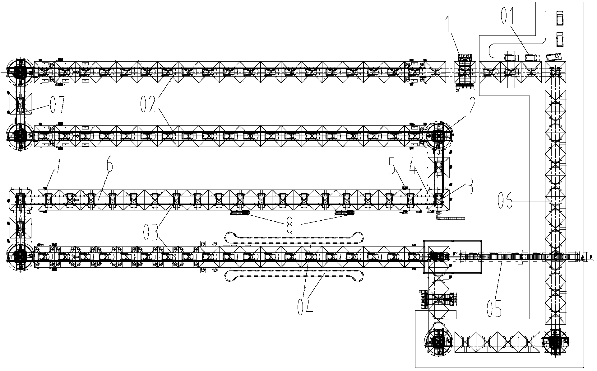
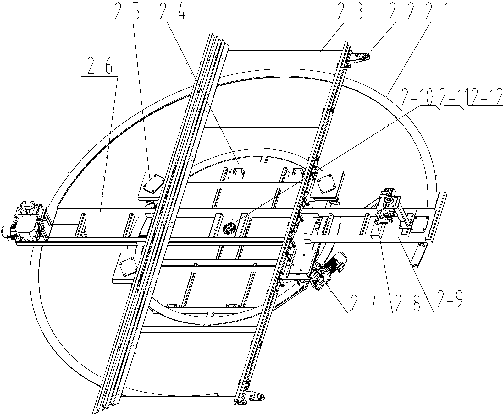
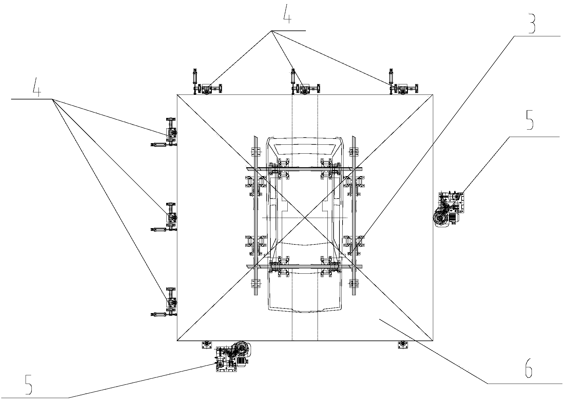
Automobile assembly sliding plate conveying line
An automobile assembly and conveying line technology, which is applied to conveyors, conveyor objects, mechanical conveyors, etc., can solve the problems of increased manufacturing cost of assembly lines, high requirements on house height, and complex structure of assembly systems, reducing installation difficulty, Improve production efficiency and optimize the effect of layout space
- Summary
- Abstract
- Description
- Claims
- Application Information
AI Technical Summary
Problems solved by technology
Method used
Image

Examples
Embodiment Construction
[0029] A detailed description will be given below in conjunction with the accompanying drawings and specific embodiments. In the following description, numerous specific details are set forth in order to provide a thorough understanding of the present invention. However, the present invention can be implemented in many other ways different from those described here, and those skilled in the art can make similar extensions without violating the connotation of the present invention, so the present invention is not limited by the specific embodiments disclosed below.
[0030] The present invention provides a new type of skateboard conveying system and sub-systems, which can integrate different assembly lines on the same skateboard conveying line, thus satisfying various process requirements at the same time, which greatly improves the assembly accuracy, work efficiency and manufacturing cost of the system. A substantial increase, which can better meet the overall performance requ...
PUM
 Abstract
Description
Claims
Application Information