

Heavy oil storage tank dehydration device
A technology for storage tanks and heavy oil, applied in the field of equipment for the separation of hydrocarbon oil and water, which can solve problems such as inability to remove water, and achieve the effects of small investment, convenient operation, and simple equipment structure
Active Publication Date: 2014-09-17
LUOYANG PETROCHEMICAL ENG CORP SINOPEC +1
View PDF5 Cites 10 Cited by
- Summary
- Abstract
- Description
- Claims
- Application Information
AI Technical Summary
Problems solved by technology
[0003] A heavy oil storage tank water removal device of the present invention, in order to overcome the defect that the water in the heavy oil storage tank with a density greater than water cannot be removed in the prior art, and remove the water in the heavy oil storage tank smoothly, the heavy oil storage tank removes The water equipment has simple structure, convenient installation, small investment and convenient operation
Method used
View moreImage
Smart ImageViewing Examples

Examples
Embodiment Construction
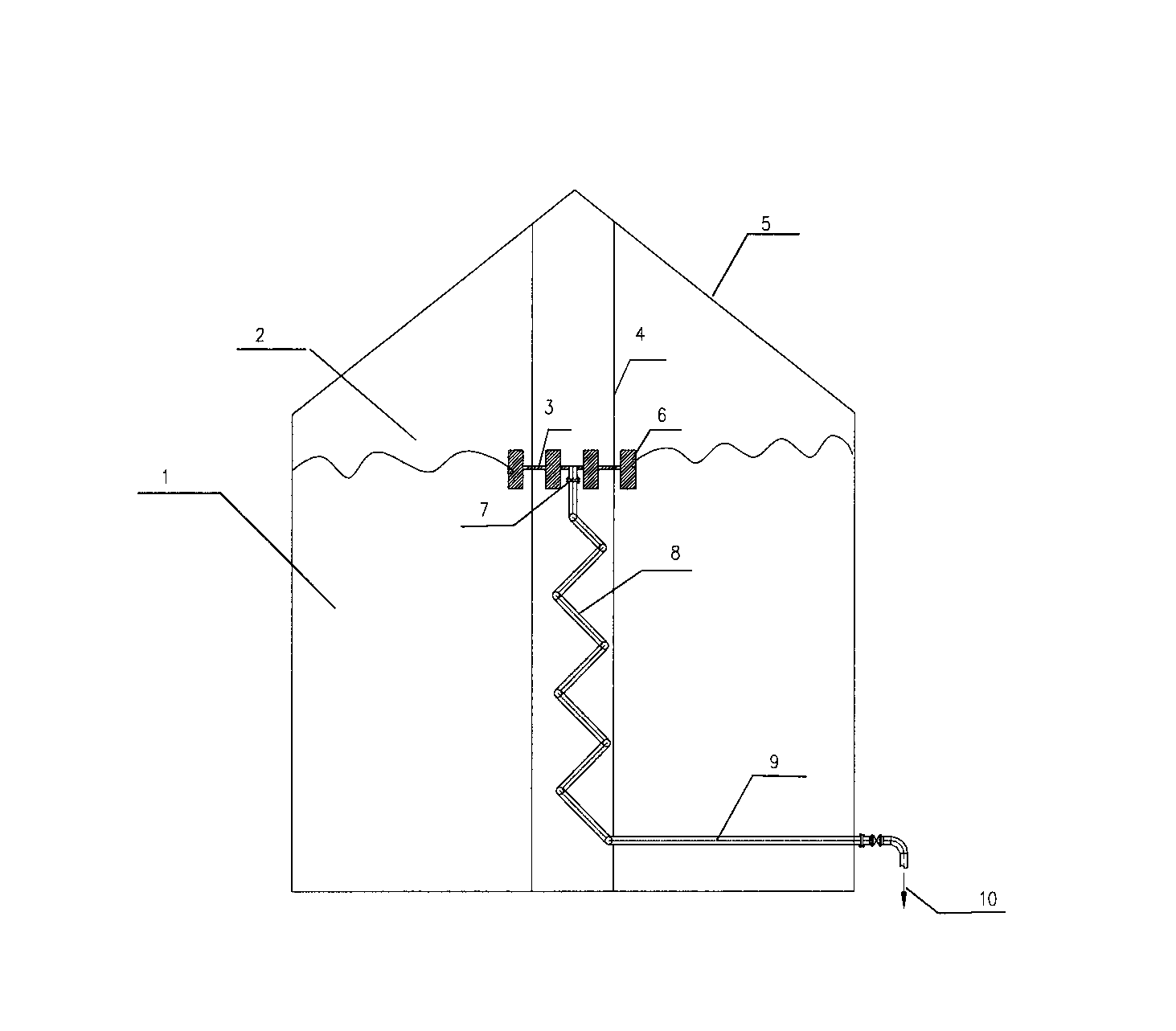
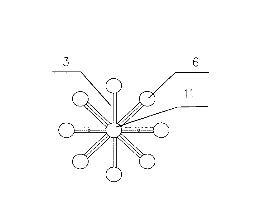
[0014] as attached figure 1 with 2 As shown, a heavy oil storage tank water removal device of the present invention is composed of a float 6, a drainage folded pipe 8, a guide rod 4, a balance arm 3 and a drainage straight pipe 9, and a water inlet 11 is arranged in the middle of the balance arm, and a water inlet 11 One end of the drain pipe 8 is connected, the other end of the drain pipe 8 is connected with the drain pipe 9, the float 6 is connected with the balance arm 3, the balance arm 3 moves along the guide rod 4, there are 8 floats 6, located at the oil-water interface, the balance arm 3, the balance arm 3 is a pipe.
Login to View More PUM
 Abstract
The invention discloses a heavy oil storage tank dehydration device which is composed of a float (6), a drainage folding tube (8), a guide bar (4), a balance arm (3) and a drainage straight tube (9). The middle of the balance arm is provided with a water inlet (11) which is communicated with one end of the drainage folding tube (8), and the other end of the drainage folding tube (8) is communicated with the drainage straight tube (9). The float (6) is communicated with the balance arm (3) which moves along the guide bar (4). The equipment provided by the invention has a simple structure, is convenient to install, has less investment, and is convenient to operate.
Description
Technical field: [0001] The invention relates to a device for separating hydrocarbon oil and water, in particular to a device for removing water in a heavy oil storage tank. technical background: [0002] At present, the density of most petroleum and its distillates is less than that of water. For this type of oil storage tank, the water is located in the lower part of the oil storage tank, and the water is dehydrated through the dehydration pipe at the lower part of the storage tank. Remove water. The proportion of heavy oil and low-quality oil is getting higher and higher, especially the heavy fraction of heavy and low-quality oil accounts for an increasing proportion of crude oil. These heavy oils have a high density, and some have a specific gravity greater than 1.0. The water in the oil will be located in the upper part of the heavy oil, and the water cannot be removed through the dehydration pipe at the lower part of the storage tank. The water will accumulate in the ...
Claims
Login to View More Application Information
Patent Timeline
 Patent Type & AuthorityApplications(China)
IPC IPC(8): C10G33/00
Inventor程继元谢伟峰何龙辉常征闫璐
OwnerLUOYANG PETROCHEMICAL ENG CORP SINOPEC