Bilaterally-rotating shower room

A two-way rotation, shower room technology, applied in the field of sanitary ware, can solve the problems of complex overall structure of the rack, no rack, and inconvenient placement, etc., and achieves the effect of good sliding effect, simple structure and long service life.

Active Publication Date: 2014-09-17
中山市优普卫浴有限公司
View PDF6 Cites 1 Cited by
  • Summary
  • Abstract
  • Description
  • Claims
  • Application Information

AI Technical Summary

Problems solved by technology

[0004] Although the above-mentioned scheme solves the deficiencies of the prior art to a certain extent, and adopts a circular movable door that can move in one direction, no shelf is provided. Shelves, shower supplies or changing clothes are often easily wet. If a shield is installed on the shelving, the overall structure of the shelving will appear complicated and inconvenient to use. At the same time, water will still seep into the clothes, which is not practical.

Method used


Image

  • Bilaterally-rotating shower room
  • Bilaterally-rotating shower room
  • Bilaterally-rotating shower room

Examples


Embodiment 1

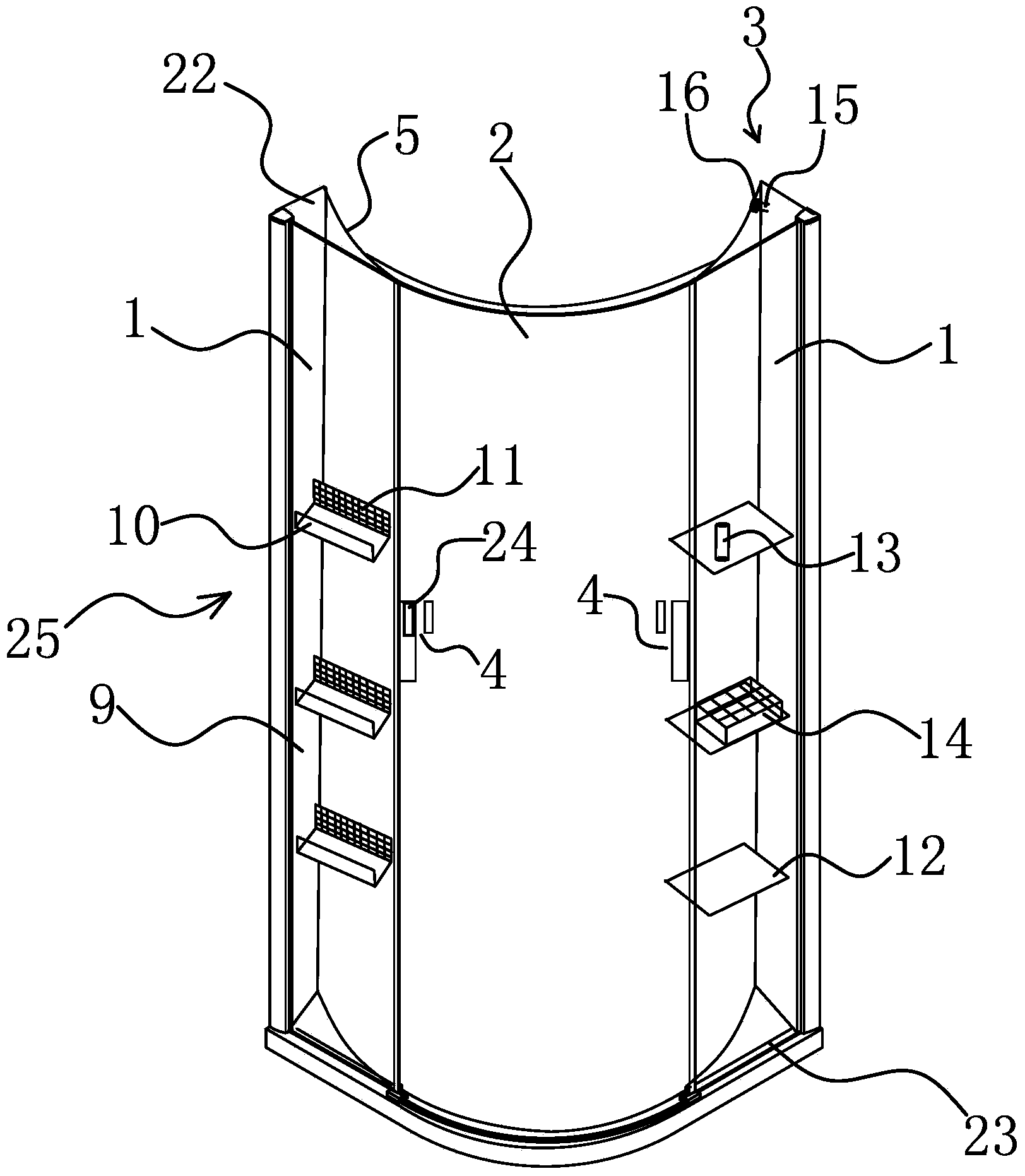
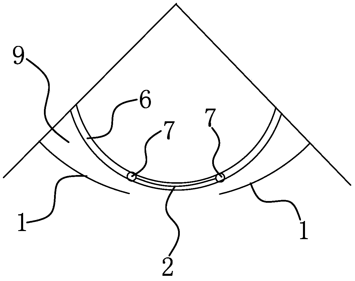
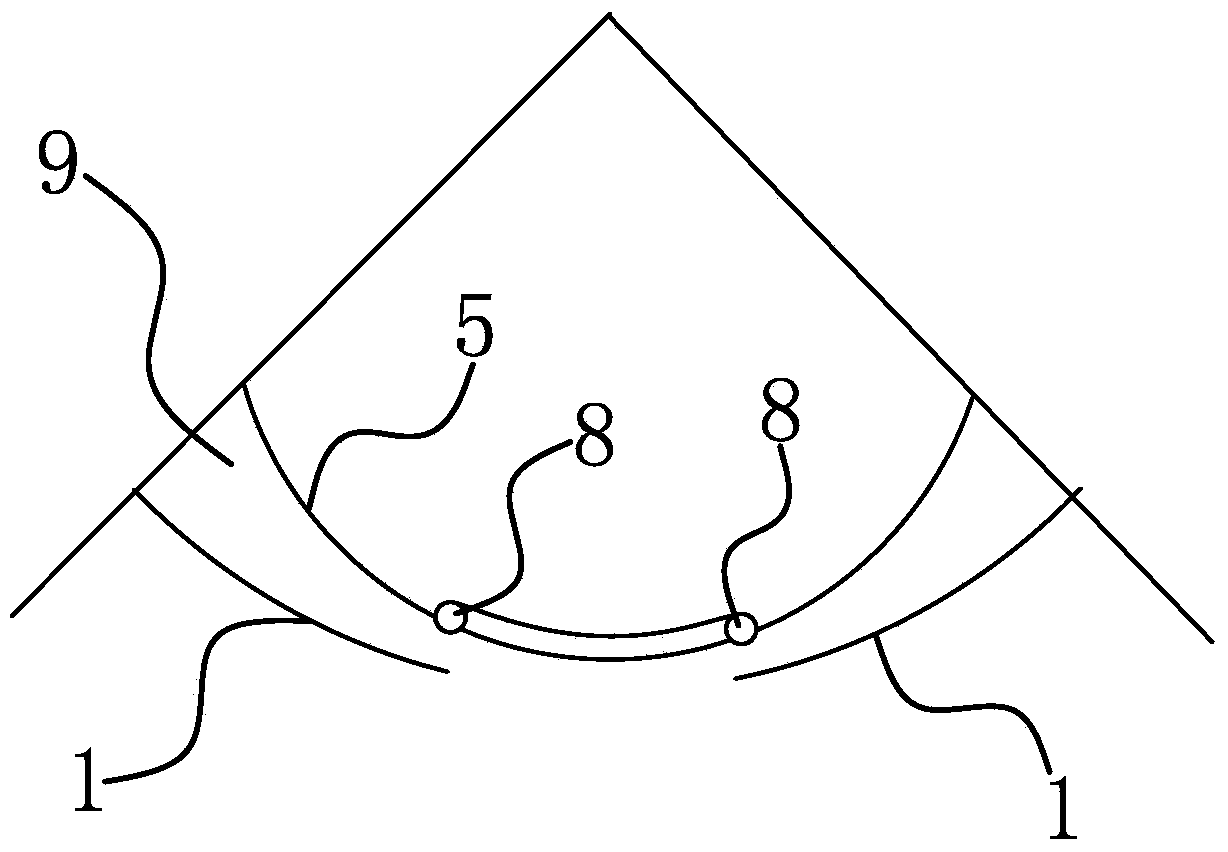
[0026] Such as figure 1 , 2 , 3, 6 or 7, the two-way rotating shower room includes an upper annular fixed frame 22 and a lower annular fixed frame 23, and an annular glass door 1 positioned at both ends is fixed between the upper annular fixed frame 22 and the lower annular fixed frame 23 , the lower annular fixed frame 23 is provided with a movable glass door 2 between the annular glass doors 1 and the movable glass door 2 can slide along the upper annular fixed frame 22 and the lower annular fixed frame 23, and the movable glass door 2 slides to the upper annular The end of the fixed frame 22 and the annular glass door 1 form an accommodating cavity 9, the accommodating cavity 9 is provided with a storage mechanism 25, and the two ends of the upper annular fixed frame 22 are respectively provided with a ring that can prevent the movable glass door 2 from sliding to the upper ring. The first blocking mechanism 3 at the end of the fixed frame 22 is provided with a handle on t...

Embodiment 2

[0030] Such as Figure 4 As shown, this embodiment is basically the same as Embodiment 1, the difference is that one side of the movable glass door 2 is set on the inner side of one of the ring glass doors 1, and the other side is set on the other ring glass door 1 outside. The movable glass door 2 can form an accommodating cavity 9 with the inner side of the ring glass door 1 on one side.

Embodiment 3

[0032] Such as Figure 5 As shown, this embodiment is basically the same as Embodiment 1, the difference is that both sides of the movable glass door 2 are arranged on the outside of the ring glass door 1 . The ring glass door 1 is provided with an opening, and the upper and lower ends of the opening are provided with a shielding curtain that can move laterally. The movable glass door 2 can form an accommodating chamber 9 with the outside of the ring glass door 1. Before taking a bath, place the shower articles or changing clothes. On the storage mechanism 25, after entering the shower space, the shade curtain can be pulled horizontally to take shower articles or change clothes.


PUM


Abstract

The invention belongs to the technical field of sanitary ware, and particularly relates to a bilaterally-rotating shower room. The bilaterally-rotating shower room is characterized by comprising an upper annular fixing frame and a lower annular fixing frame; annular glass doors located at the two ends are fixed between the upper annular fixing frame and the lower annular fixing frame, a movable glass door located between the annular glass doors is arranged on the lower annular fixing frame and can slide along the upper annular fixing frame and the lower annular fixing frame, the movable glass door and the annular glass doors form a containing cavity after the movable glass door slides to the end of the upper annular fixing frame, a storage mechanism is arranged in the containing cavity, and the two ends of the upper annular fixing frame are provided with first stopping mechanisms capable of stopping the movable glass door from sliding to the ends of the upper annular fixing frame. The bilaterally-rotating shower room has the advantages that the structure is simple, bilaterally-rotating movement can be achieved, storage is convenient, and shower tools or laundry on the storage mechanism is not prone to being wet by water.

Description

technical field [0001] The invention belongs to the technical field of sanitary ware, and in particular relates to a two-way rotating shower room. Background technique [0002] The shower room is a separate shower compartment. Modern homes have higher and higher requirements for bathroom facilities. Many families hope to have an independent bathing space. However, due to the limited sanitary space in the living room, the bathing facilities and sanitary ware can only be placed together. room. The shower room makes full use of a corner of the room, and uses a fence to clearly divide the shower range to form a relatively independent bathing space. According to the function, the shower room is divided into integral shower room and simple shower room; according to the style, it is divided into corner shower room, one-shaped bath screen, arc-shaped shower room, bathtub upper bath screen, etc.; according to the shape of the chassis, it is divided into square and full circle Shape...

Claims


Application Information

Patent Timeline
Patent Type & Authority Applications(China)
IPC IPC(8): E04H1/12E06B3/46E06B7/28E05C17/60
Inventor 俞人炜
Owner 中山市优普卫浴有限公司
Why Eureka
Try Eureka