Novel hydro-pneumatic spring

An oil-gas spring, a new type of technology, used in springs, springs/shock absorbers, gas-liquid shock absorbers, etc., can solve the problems of damping valves being easily affected by oil movement, and metal valve plates being easily fatigued and damaged. Simple, low-volume, compact layout

Inactive Publication Date: 2014-09-17
JIANGSU UNIV
View PDF5 Cites 26 Cited by
  • Summary
  • Abstract
  • Description
  • Claims
  • Application Information

AI Technical Summary

Problems solved by technology

[0004] The purpose of the present invention is to overcome the shortcomings of the oil-gas spring in the prior art that the metal valve plate is easily fatigued and damaged under heavy loads and the movement of the damping valve is easily affected by the movement of the oil, a...

Method used


Image

  • Novel hydro-pneumatic spring
  • Novel hydro-pneumatic spring
  • Novel hydro-pneumatic spring

Examples


Embodiment Construction

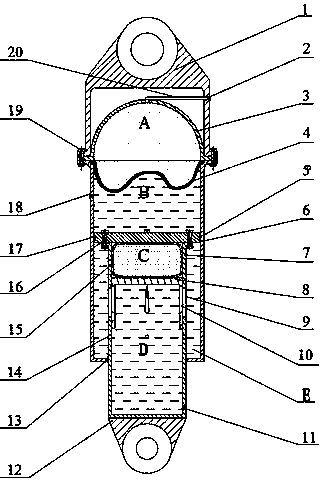
[0019] see figure 1 The overall structure sectional view of the present invention, the upper end of the present invention is the upper ring fixing device 1, the middle is the working cylinder 5, the lower end is the lower ring fixing device 12, and the lower end of the upper ring fixing device 1 is fixedly connected to the working cylinder through a threaded assembly 19 5, the upper ring fixing device 1 is hinged with the vehicle frame, and the lower ring fixing device 12 is hinged with the vehicle axle.

[0020] A piston 6 is installed in the inner chamber of the working cylinder 5, the piston 6 is fixedly connected to the upper end of the piston rod 7, the lower end of the piston rod 7 protrudes downwards outside the working cylinder 5, and the lower end of the piston rod 7 is fixedly connected to the lower ring fixing device 12 . Use sealing ring 13 to seal at the junction of piston rod 7 side walls and working cylinder barrel 5 lower bottom surfaces. The outer wall of th...


PUM


Abstract

The invention discloses a novel hydro-pneumatic spring. An upper semispherical chamber is arranged in an inner cavity of an upper hoisting ring fixing device, a rubber hydro-pneumatic diaphragm is arranged at the upper opening of a working cylinder, a sealed high-pressure air chamber inflated with high-pressure air is formed by the upper semispherical chamber and the rubber hydro-pneumatic diaphragm, a closed rodless cavity is defined by the rubber hydro-pneumatic diaphragm, the inner wall of the working cylinder and a piston located under the rubber hydro-pneumatic diaphragm, an annular cavity is defined by the piston, the outer wall of a piston rod, the inner wall of the working cylinder and the lower wall, an air bag and a damping valve are arranged in an inner cavity of the piston rod, four second trapezoid through holes evenly distributed in the radial direction are formed in the lateral wall of the damping valve, and four first trapezoid through holes which are evenly distributed in the radial direction and are in the same radial positions as the four second trapezoid through holes are formed in the lateral wall of the piston rod. Pressure difference is generated between the pressure of the air in the air bag and the pressure of liquid in the annular cavity, the air bag is pressed or expands, continuous variation of the area of a throttling hole is achieved, the smoothness of a car can be improved, and the service life of the hydro-pneumatic spring is prolonged.

Description

technical field [0001] The invention relates to the field of automobile suspension systems, in particular to an oil-pneumatic spring with variable damping. Background technique [0002] In the automobile suspension system, the oil-gas spring is a suspension elastic damping element with excellent performance. It is the core part of the oil-gas suspension. It has both damping characteristics and nonlinear stiffness characteristics. The flow resistance of the oil is used to achieve vibration reduction, while the incompressibility of the oil is used to achieve more accurate motion and force transmission. The oil-pneumatic spring has the characteristic of variable stiffness, so that the vehicle equipped with the oil-pneumatic suspension can obtain a lower natural vibration frequency, thereby improving the driver's working conditions and increasing the average speed, and the oil-pneumatic spring can also realize the adjustment of the vehicle body height. [0003] Existing oil-gas...

Claims


Application Information

Patent Timeline
IPC IPC(8): F16F9/08F16F9/34F16F9/32
Inventor 李仲兴郭子权马孜立江洪
Owner JIANGSU UNIV
Why Eureka
Try Eureka