Device for measuring pipe thermal displacement

A technology for measuring pipelines and thermal displacements, applied to measuring devices, optical devices, instruments, etc., can solve problems such as large errors, achieve long service life, low manufacturing costs, and easy installation and use

Inactive Publication Date: 2014-09-17
CHINA INSTITUTE OF ATOMIC ENERGY
View PDF9 Cites 4 Cited by
  • Summary
  • Abstract
  • Description
  • Claims
  • Application Information

AI Technical Summary

Problems solved by technology

The advantage of this method is that it is simple and easy to implement, but the disadvantage is that the error is large

Method used


Image

  • Device for measuring pipe thermal displacement
  • Device for measuring pipe thermal displacement
  • Device for measuring pipe thermal displacement

Examples


Embodiment Construction

[0013] The present invention will be described in detail below with reference to the drawings and embodiments.

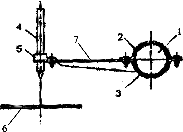
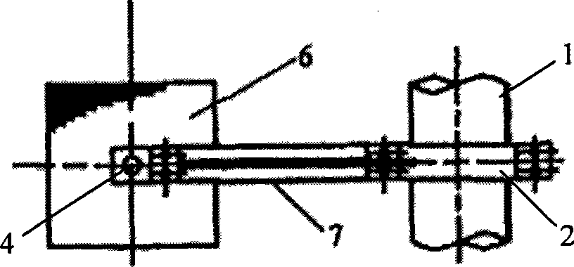
[0014] The pipeline thermal displacement measuring device provided by the present invention is aimed at the large thermal displacement of the CEFR main heat transfer system pipeline. It has a simple structure, easy installation and operation, low manufacturing cost, wide application range, long service life and no measuring range. Limited thermal displacement measuring device. Such as figure 1 , figure 2 As shown, the pipeline thermal displacement measuring device is mainly composed of upper and lower pipe clamps 2, 3, light pen pointer 4 and coordinate paper 6. The upper and lower pipe clamps 2, 3 are fixed on the pipe 1. The upper and lower pipe clamps 2, 3 are required to be fixed relative to the pipe 1 to ensure that no sliding or rotation occurs under working conditions; the light pen pointer 4 is installed on the pipe clamp through the light pen holder 5 The o...


PUM


Abstract

The invention relates to a device for measuring pipe thermal displacement. The device includes a light-gun pointer fixedly connected with a tested pipe. The light spot projection direction of the light-gun pointer is vertical to the direction of the pipe thermal displacement. A piece of coordinate paper is arranged on a light-spot projection position of the light-gun pointer. The measurement device does not include precision electronic elements such as sensors so that the device is simple in design, low in manufacturing cost, and convenient to install and use; and the measurement precision (1mm) of the device is capable of meeting thermal displacement measurement demands of the CEFR. The measurement device is long in service life and capable of being used repeatedly for a long term as long as attention is paid to protection of the device in an operation process.

Description

Technical field [0001] The invention relates to a displacement measuring device, in particular to a device for measuring the thermal displacement of a pipeline. Background technique [0002] The China Experimental Fast Reactor (CEFR) uses sodium as the coolant, and the temperature of its main heat transfer system pipes is as high as 515°C, which is much higher than the temperature of the main pipes of the PWR nuclear power plant. An important work of CEFR during commissioning and operation is to ensure the safety and reliability of the main heat transfer system pipeline to avoid serious economic losses and catastrophic consequences caused by the failure of the inability to work. [0003] The CEFR system pipeline has high working temperature and large thermal displacement. The influence of thermal displacement on pipeline support and hanger configuration and pipeline stress is related to pipeline safety. In the actual operation of the pipeline system, due to various complex factor...

Claims


Application Information

Patent Timeline
Patent Type & Authority Applications(China)
IPC IPC(8): G01B11/02
Inventor 叶原武余华金齐敏唐龙王月英周立军
Owner CHINA INSTITUTE OF ATOMIC ENERGY
Why Eureka
Try Eureka